
Front hub bearings
- Make
- Rover
- Model
- Coupé, Cabriolet & Tourer 200/400 Coupé, Cabriolet & Tourer Workshop Manual
- Section
- Repairs › Front hub bearings
SuspensionFront hub bearings · page 1 of 2
- Fit damper top mounting nuts and tighten to 32 Nm.
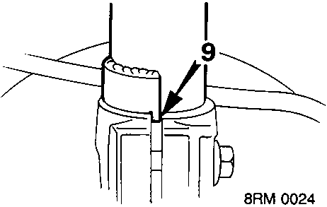
- Locate base of damper in hub. Ensure pip engages slot correctly.
- Fit bolt hub to damper and tighten to 80 Nm.
- ABS: Align ABS sensor lead bracket, fit bolt and tighten to 9 Nm.
- Align brake hose bracket to damper. Fit bolt bracket to damper and tighten to 22 Nm.
- Align anti – roll bar link with lower arm, fit bolt and tighten to 45 Nm.
- Fit road wheel and tighten nuts to 100 Nm.
- Remove stand(s) and lower vehicle.
FRONT HUB BEARINGS
Service Repair No. 60.25.14
Remove
- Raise front of vehicle.
WARNING: Support on safety stands.
- Remove road wheel(s).
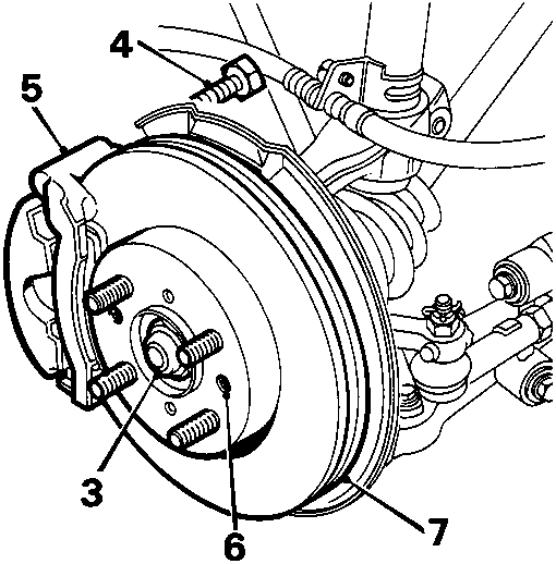
- Remove drive shaft nut and discard.
- Remove 2 bolts caliper to hub.
- Release caliper from hub and tie it aside.
- Remove 2 screws brake disc to hub.
- Mark disc to hub relationship. Remove disc from hub.
ABS 2E models:
- Remove screw, ABS sensor lead to damper bracket.
- Remove 3 screws, ABS sensor lead to hub.
- Remove screw, ABS sensor.
- Release sensor from bracket.
- Remove 2 screws, sensor bracket to hub and collect bracket.
ABS 6 models:
- Remove screw, ABS sensor lead to damper bracket.
- Remove 3 screws, ABS sensor lead to hub.
- Remove 2 screws, sensor to hub.
All models:
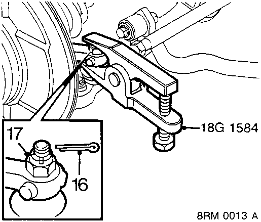
- Remove and discard split pin from steering arm nut.
- Remove steering arm joint nut.
- Break taper joint using tool 18G 1584.
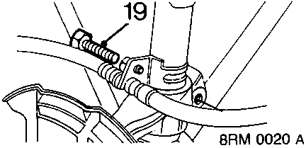
- Remove bolt hub to damper.
Parts & tools for this job For Rover Coupé, Cabriolet & Tourer
- PARTFront wheel bearingSearch: Rover Coupé, Cabriolet & Tourer front wheel bearing
- TOOLBearing puller kitSearch: wheel bearing puller kit
- PARTCV boot kitSearch: Rover Coupé, Cabriolet & Tourer cv boot kit
Links open Amazon search results in a new tab. As an Amazon Associate I earn from qualifying purchases.