
Refit
- Make
- Rover
- Model
- Coupé, Cabriolet & Tourer 200/400 Coupé, Cabriolet & Tourer Workshop Manual
- Section
- Repairs › Refit
SuspensionRefit · page 1 of 2
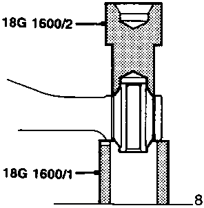
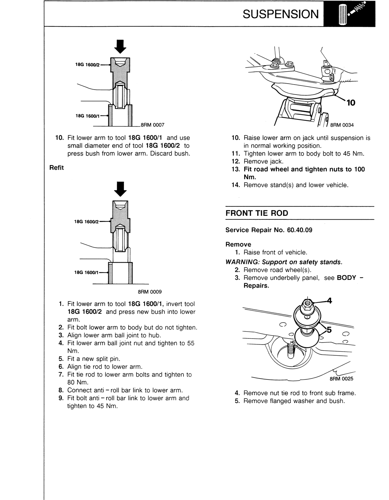
- Fit lower arm to tool 18G 1600/1 and use small diameter end of tool 18G 1600/2 to press bush from lower arm. Discard bush.
Refit
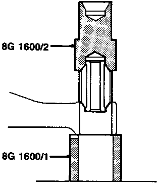
- Fit lower arm to tool 18G 1600/1, invert tool 18G 1600/2 and press new bush into lower arm.
- Fit bolt lower arm to body but do not tighten.
- Align lower arm ball joint to hub.
- Fit lower arm ball joint nut and tighten to 55 Nm.
- Fit a new split pin.
- Align tie rod to lower arm.
- Fit tie rod to lower arm bolts and tighten to 80 Nm.
- Connect anti – roll bar link to lower arm.
- Fit bolt anti – roll bar link to lower arm and tighten to 45 Nm.
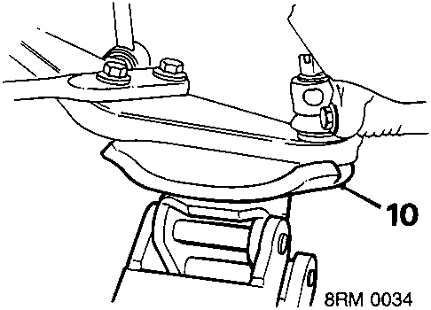
- Raise lower arm on jack until suspension is in normal working position.
- Tighten lower arm to body bolt to 45 Nm.
- Remove jack.
- Fit road wheel and tighten nuts to 100 Nm.
- Remove stand(s) and lower vehicle.
FRONT TIE ROD
Service Repair No. 60.40.09
Remove
- Raise front of vehicle.
WARNING: Support on safety stands.
- Remove road wheel(s).
- Remove underbelly panel, see BODY – Repairs.
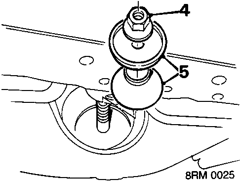
- Remove nut tie rod to front sub frame.
- Remove flanged washer and bush.
Original page
Parts & tools for this job For Rover Coupé, Cabriolet & Tourer
- TOOLCoil spring compressorSearch: coil spring compressor
- TOOLBall joint separatorSearch: ball joint separator
- PARTShock absorbersSearch: Rover Coupé, Cabriolet & Tourer shock absorbers
Links open Amazon search results in a new tab. As an Amazon Associate I earn from qualifying purchases.