
Functional description
- Make
- Alfa Romeo
- Model
- 145/146 Electrical System Diagnosis Manual, Volume 3
- Year
- 1994–2001
- Section
- Air Conditioner › Functional description
Functional description
Fan:
The heater and ventilation fan Q1 is supplied with battery voltage through the key-operated services relay I35 - located in fusebox G1 -; in addition to the supply line relay also through fuse F13 of fusebox G1.
In the versions with fusebox "B" downstream of fuse F13, there is also a special relay I78 which controls fan Q1 with a supply protected by fuse G255 (30A).
The motor of fan Q1 is operated with an earth signal leading from the control knob Q4. This signal crosses the speed regulator Q5, which is formed of three resistances in series and which determine the four different speeds depending on the signal from knob Q4: from pin 2 of connector B (1st speed), from pin 1 of connector B (2nd speed), from pin C of connector A (3rd speed) and lastly from pin B of connector A (4th speed) with a direct signal that does not cross the regulator Q5.
NOTE : the regulator Q5 has a built-in thermometric safety switch which de-activates the circuit if a temperature of 90±5°C is exceeded due to excess voltage (it closes again when the temperature falls by appr. 10°C).
Recirculation:
The recirculation function is achieved by actuating motor Q27, according to the following supply logic:
- pin 2 of Q27 always earthed;
- 12 V at pin 3 of Q27: the motor turns operating recirculation;
- 12 V at pin 1 of Q27: the motor turns shutting off recirculation.
Turning on takes place through switch Q68 but with switch Q4 on "0", "1", etc...:
- switch Q68 not pressed: recirculation not turned on;
- switch Q68 pressed: recirculation turned on.
N.B.: With switch Q4 at "OFF" recirculation is operational regardless of the position of switch Q68.
First fan speed with the compressor operating:
With control Q4 in the "0" position the fan Q1 is stopped but it is operated at first speed if the compressor is turned on: in this case a special relay
Controls lighting:
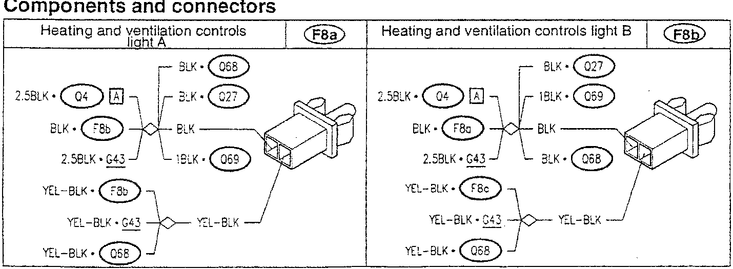
Lights F8a and F8b, located inside the control panel, together with the led next to switch Q68 are supplied by the side lights circuit - connector D of fusebox G1.
Components and connectors
Parts & tools for this job For 1994 Alfa Romeo 145/146
- TOOLDigital multimeterSearch: automotive digital multimeter
- PARTAssorted fuse kitSearch: car fuse assortment kit
- TOOLWire crimper and connector kitSearch: wire crimper connector kit
Links open Amazon search results in a new tab. As an Amazon Associate I earn from qualifying purchases.