
Description
- Make
- Alfa Romeo
- Model
- GTV / Spider GTV and Spider (916) Factory Service Manual
- Year
- 1995–2000
- Section
- Removal/Refitting › Description
Variants – 3.0 V6 24VDescription · page 1 of 16
DESCRIPTION
The information and illustrations given below make it possible to quickly remove the power plant from its housing and subsequent refitting.
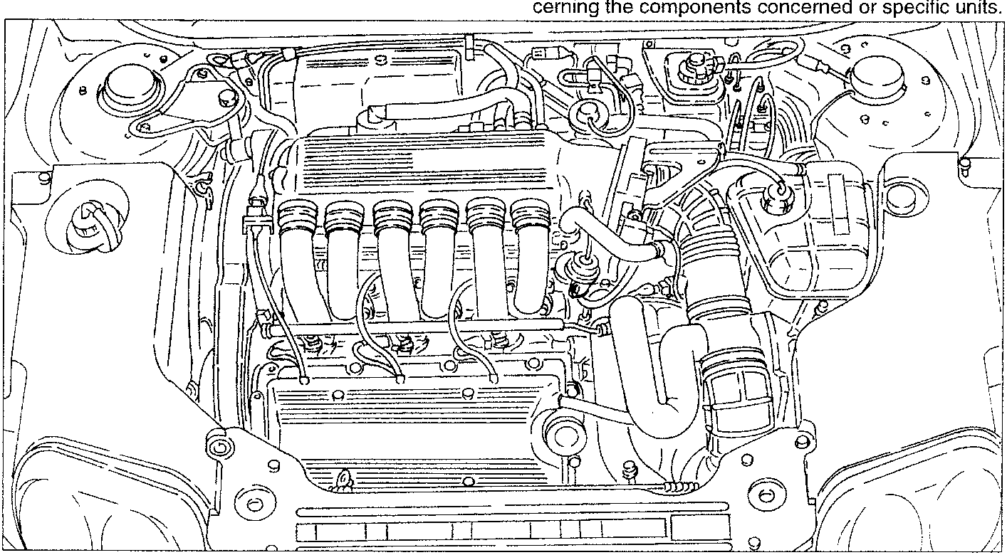
Disassembly of the engine on the bench is described in the volume "ENGINE OVERHAULING". The following procedure gives the possibility to be used only in part depending on requirements. For further information and details see the chapters concerning the components concerned or specific units.
REMOVAL
- Set the car on a lift.
- Disconnect the battery (-) terminal.
- Remove the front wheels and mud flaps.
- Remove the engine compartment trim.
- Remove the right front wheel house.
- Drain the coolant fluid (R134a) of the air conditioning system (see specific paragraph).
- Raise the car and drain the coolant fluid, disconnecting the radiator outlet sleeve and collect it in a suitable container.
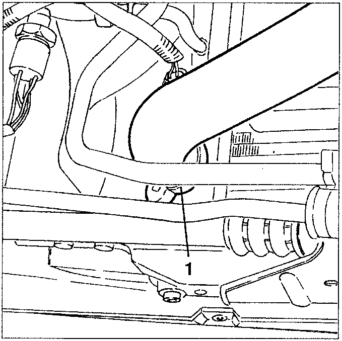
- Part 1: radiator outlet sleeve
- From the corrugated sleeve disconnect the oil vapour recovery pipe leading from the cylinder head.
- Disconnect the electrical connection from the intake air temperature sensor.
- From the corrugated sleeve disconnect the air intake pipe for the constant idle speed device.
- Disconnect the electrical connection from the throttle potentiometer.
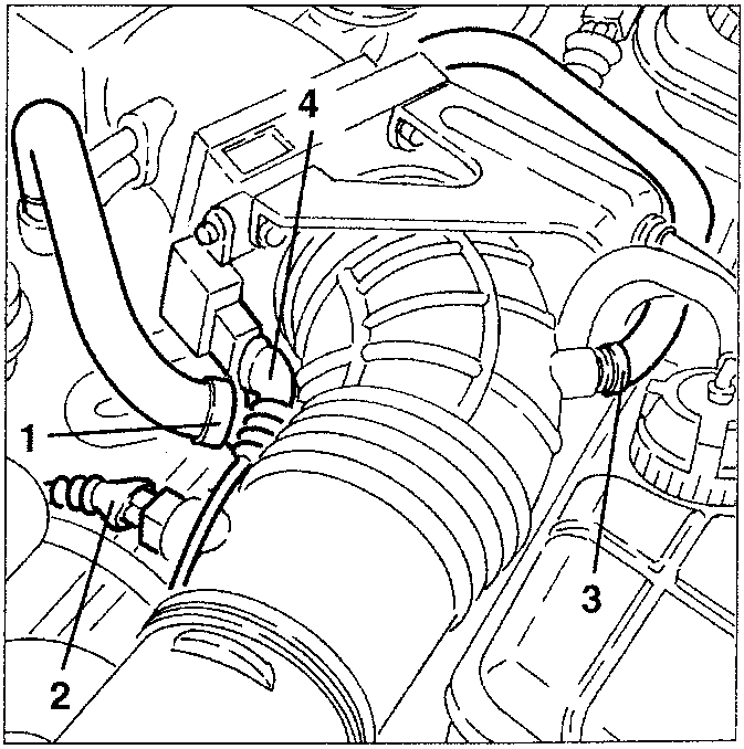
- Part 1: oil vapour recovery pipe
- Part 2: intake air temperature sensor connector
- Part 3: constant idle speed device connection point
- Part 4: throttle potentiometer electrical plug
Parts & tools for this job For 1995 Alfa Romeo GTV / Spider
- TOOLTorque wrenchSearch: 3/8 inch torque wrench
- TOOLSocket setSearch: socket set metric
- BOOKHaynes manualSearch: Haynes manual Alfa Romeo GTV / Spider
Links open Amazon search results in a new tab. As an Amazon Associate I earn from qualifying purchases.