
Introduction - diesel pressure pump and control
- Make
- Fiat
- Model
- Bravo Factory Service Manual
- Year
- 2007–2014
- Section
- Diesel injection system › Introduction - diesel pressure pump and control
INTRODUCTION - DIESEL PRESSURE PUMP AND CONTROL
DESCRIPTION OF COMPONENTS
HIGH PRESSURE PUMP
Introduction
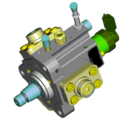
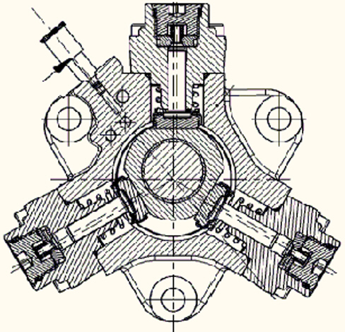
The supply pump for the Common Rail system is known as a Radial jet pump because the pumping effect is achieved using three pumping elements (pistons) arranged in a radial direction in relation to the pump shaft rotation axis. The angle between one pumping element and the other is 120°.
Function
The pump is driven by the engine at a rotation speed of 2/3 (4v) and 25/43 (2v) of that of the actual engine, by means of a toothed belt transmission. The timing and the duration of the injection are, in this injection system, operated by the electronic control system; this pump only carries out the function of keeping the fuel in the manifold permanently at the required pressure level.
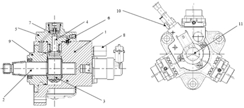
- 1 Pump casing
- 2 Pump shaft
- 3 Cam
- 4 Piston
- 5 Cover
- 6 High pressure regulation valve
- 7 Inlet valve
- 8 Supply - high pressure (to single fuel manifold)
- 9 Pump casing cover
- 10 Safety valve
- 11 Low pressure regulator solenoid
Requirements
The pump is supplied at a low pressure, receiving a minimum pressure of 3.5 bar and a minimum flow rate of 160lt/h at the input, in order to ensure correct operation. This supply is achieved by means of a low pressure electric pump.
Radial jet pump specifications
The movement of the pistons is determined by the rotation of a triangular-shaped cam integrated with the pump shaft. This cam causes the movement of the three pistons in succession, through the movement of a mechanical interface (tappet) between the cam and the foot of the piston. The contact between the cam and each individual tappet is ensured by means of a spring.
Each pumping unit is equipped with a plate-type intake valve and a ball-type delivery valve. All three supplies for the pumping elements are joined inside the pump and send the fuel to the shared manifold by means of a single duct. One feature of this pump is that it is simultaneously lubricated and cooled by the same diesel fuel circulating inside it, by means of suitable ports.
There is a low pressure regulator solenoid on the pump to adjust the supply pressure at the pump intake, in order to compress only the amount of diesel fuel needed to reach the pressure mapped in the control unit.
The main specifications of the Radial jet pump are described below:
type: radialjet with radial pumping elements
number of pumping elements: 3
Total capacity: 0.697 cm3/rev
Volumetric output: less than 80% at 16000 bar at 2000 pump rpm with diesel fuel at 40°C
Maximum operating pressure: 1600 bar
Power absorbed: 1.6kW at 1600 bar, 3450 engine rpm
Supply: diesel fuel at a pressure of 3.5 bar with a minimum flow rate of 160lt/h
Lubrication: carried out by the same diesel fuel supply
Cooling: carried out by the same diesel fuel supply
The maximum speed depending on the pressure is indicated below:
| Speed (rpm) | Pressure (bar) |
|---|---|
| 400 | 550 |
| 500 | 650 |
| 800 | 885 |
| 1000 | 1038 |
| 1173 | 1134 |
| 1340 | 1231 |
| 1750 | 1514 |
| 1860 | 1600 |
| 3200 | 1600 |
| 3700 | 770 |
| 4000 | 400 |
| 4200 | 400 |
| 4400 | 100 |
DESCRIPTION OF COMPONENTS
HIGH PRESSURE PUMP
Introduction
The supply pump for the Common Rail system is known as a Radial jet pump because the pumping effect is achieved using three pumping elements (pistons) arranged in a radial direction in relation to the pump shaft rotation axis. The angle between one pumping element and the other is 120°.
Function
The pump is driven by the engine at a rotation speed equal to 2/3 (4v) and 25/43 (2v) of that of the actual engine, by means of a toothed belt transmission. The timing and the duration of the injection are, in this injection system, regulated by the electronic control system; this pump only carries out the function of keeping the fuel in the manifold permanently at the required pressure level.
- 1 Pump casing
- 2 Pump shaft
- 3 Cam
- 4 Piston
- 5 Cover
- 6 High pressure regulation valve
- 7 Inlet valve
- 8 Supply - high pressure (to single fuel manifold)
- 9 Pump casing cover
- 10 Safety valve
- 11 Low pressure regulator solenoid
Requirements
The pump is supplied at a low pressure, receiving a minimum pressure of 3.5 bar and a minimum flow rate of 160lt/h at the input, in order to ensure correct operation. This supply is achieved by means of a low pressure electric pump.
Radial jet pump specifications
The movement of the pistons is determined by the rotation of a triangular-shaped cam integrated with the pump shaft. This cam causes the movement of the three pistons in succession, through the movement of a mechanical interface (tappet) between the cam and the foot of the piston. The contact between the cam and each individual tappet is ensured by means of a spring.
Each pumping unit is equipped with a plate-type intake valve and a ball-type delivery valve. All three supplies for the pumping elements are joined inside the pump and send the fuel to the shared manifold by means of a single duct. One feature of this pump is that it is simultaneously lubricated and cooled by the same diesel fuel circulating inside it, by means of suitable ports.
There is a low pressure regulator solenoid on the pump to adjust the supply pressure at the pump intake, in order to compress only the amount of diesel fuel needed to reach the pressure mapped in the control unit.
The main specifications of the Radial jet pump are described below:
type: radialjet with radial pumping elements
number of pumping elements: 3
Total capacity: 0.697 cm3/rev
Volumetric output: less than 80% at 16000 bar at 2000 pump rpm with diesel fuel at 40°C
Maximum operating pressure: 1600 bar
Power absorbed: 1.6kW at 1600 bar, 3450 engine rpm
Supply: diesel fuel at a pressure of 3.5 bar with a minimum flow rate of 160lt/h
Lubrication: carried out by the same diesel fuel supply
Cooling: carried out by the same diesel fuel supply
The maximum speed depending on the pressure is indicated below:
| Speed (rpm) | Pressure (bar) |
|---|---|
| 400 | 550 |
| 500 | 650 |
| 800 | 885 |
| 1000 | 1038 |
| 1173 | 1134 |
| 1340 | 1231 |
| 1750 | 1514 |
| 1860 | 1600 |
| 3200 | 1600 |
| 3700 | 770 |
| 4000 | 400 |
| 4200 | 400 |
| 4400 | 100 |
Parts & tools for this job For 2007 Fiat Bravo
- PARTGlow plugsSearch: Fiat Bravo 2007 glow plugs
- TOOLGlow plug socketSearch: glow plug socket
- TOOLDiesel compression testerSearch: diesel compression tester
Links open Amazon search results in a new tab. As an Amazon Associate I earn from qualifying purchases.