
System cable loom - r.r.
- Make
- Fiat
- Model
- Bravo Factory Service Manual
- Year
- 2007–2014
- Section
- Diesel injection system › System cable loom - r.r.
SYSTEM CABLE LOOM - R.R.
Removing
- Position the vehicle on a lift.
Op. 1016A10 SOUND-PROOFING COVER - R.R
Op. 4450B02 LEFT FRONT WHEEL - R.R
Op. 7055B54 UNDER ENGINE PROTECTION/GUARD - R.R.
Op. 7055B65 ENGINE COMPARTMENT DUST COVER IN LEFT FRONT WHEEL ARCH - R.R.
Op. 1048A10 AIR FILTER ASSEMBLY - R.R.
Op. 1008C30 POWER UNIT LOWER REACTION LINK - R.R.
Op. 1008C33 BRACKET ON ENGINE FOR LOWER REACTION ROD - R.R.
1. Disconnect the electrical connection for the engine rpm sensor.
| Description | Connector | |
|---|---|---|
| 1 | Rpm sensor | See K046 RPM SENSOR |
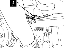
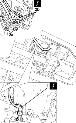
1. Disconnect the electrical connection for the engine oil pressure warning light switch.
| Description | Connector | |
|---|---|---|
| 1 | Engine oil pressure sensor (switch) | See K030 ENGINE OIL PRESSURE SENSOR (SWITCH) |
2. Undo nuts (2a) and disconnect electrical connections (2b) from alternator.
| Description | Connector | |
|---|---|---|
| 2b | Alternator | See A010 ALTERNATOR |
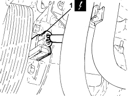
1. Disconnect the electrical connection for the air conditioning compressor engagement electromagnet.
| Description | Connector | |
|---|---|---|
| 1 | Air conditioning compressor engagement electro-magnet | See L020 AIR CONDITIONING COMPRESSOR ENGAGEMENT ELECTRO-MAGNET |
- Open the cable clips securing the engine oil dipstick tube.
- Undo the bolt and remove the earth lead from the air conditioner compressor.
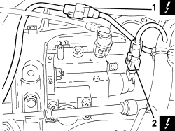
1. Detach the timing sensor electrical connection.
| Description | Connector | |
|---|---|---|
| 1 | Timing sensor | See K047 TIMING SENSOR |
2. Detach the fuel pressure sensor electrical connection on the pressure pump.
| Description | Connector | |
|---|---|---|
| 2 | Fuel pressure regulator | See N077 FUEL PRESSURE REGULATOR |
1. Disconnect the electrical connections from the injectors and open the cable retaining clips.
| Description | Connector | |
|---|---|---|
| 1 | Injector | See N070 INJECTOR |
2. Undo the bolts securing the drip channel cabling to the intake chamber.
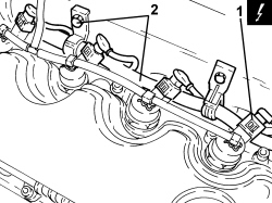
1. Disconnect the E.G.R. solenoid electrical connection.
| Description | Connector | |
|---|---|---|
| 1 | EGR solenoid | See L030 EGR SOLENOID VALVE |
2. Detach the pressure relief sensor electrical connection.
| Description | Connector | |
|---|---|---|
| 2 | Turbocharging sensor | See K044 AIR TEMPERATURE/PRESSURE SENSOR |
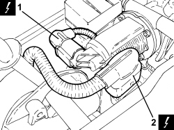
1. Detach the fuel pressure sensor electrical connection.
| Description | Connector | |
|---|---|---|
| 1 | Fuel pressure sensor | See K083 FUEL PRESSURE SENSOR |
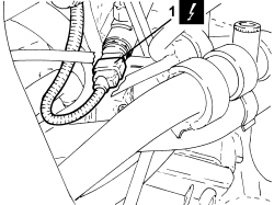
1. Disconnect the engine coolant temperature sensor electrical connection.
| Description | Connector | |
|---|---|---|
| 1 | Engine coolant temperature sensor/sender unit | See K036 ENGINE COOLANT TEMPERATURE SENSOR/SENDER UNIT |
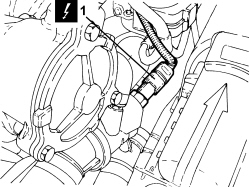
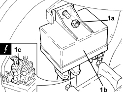
1. Undo nut (1a), remove glow plug preheating control unit (1b) and disconnect electrical connection (1c).
| Description | Connector | |
|---|---|---|
| 1c | Glow plug preheating control unit | See M015 PLUG PREHEATING CONTROL UNIT |
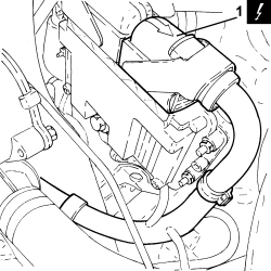
1. Connect the electrical connection for the injection control unit.
| Description | Connector | |
|---|---|---|
| 1 | Engine management control unit | See M010 ENGINE MANAGEMENT ECU |
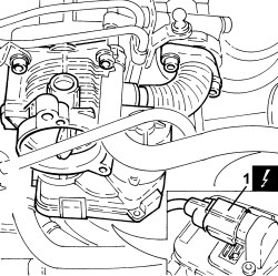
1. Detach the electrical connection for the throttle body.
| Description | Connector | |
|---|---|---|
| 1 | Integrated throttle body actuator | See N075 BUILT-IN THROTTLE BODY ACTUATOR |
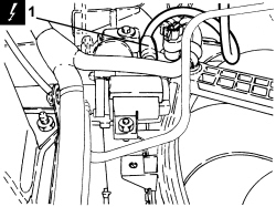
1. Disconnect the electrical connection for the turbo variable geometry control solenoid.
| Description | Connector | |
|---|---|---|
| 1 | Turbine variable geometry control solenoid | See L036 TURBINE VARIABLE GEOMETRY CONTROL SOLENOID VALVE |
1. Detach the electrical connection for the exhaust gas temperature sensor.
| Description | Connector | |
|---|---|---|
| 1 | Upstream particulate filter (DPF) temperature sensor | See K189 UPSTREAM PARTICULATE FILTER TEMPERATURE SENSOR (DPF) |
- Detach the electrical connections from the glowheater plugs.
| Description | Connector | |
|---|---|---|
| Glowheater plugs | See A040 HEATER PLUGS |
- Open the remaining retaining clips and remove the wiring loom.
Refitting
- Fit the cable loom in place and secure using the retaining clips.
- Connect the glowheater plug electrical connections.
- Connect the electrical connection for the exhaust gas temperature sensor.
- Connect the turbo variable geometry control solenoid electrical connection.
- Connect the electrical connection for the throttle body.
- Connect the electrical connection for the injection control unit.
- Connect the electrical connection, place the glow plug preheating control unit in position and secure by tightening the nut.
- Connect the engine coolant temperature sensor electrical connection.
- Secure the electrical connection for the fuel pressure sensor.
- Connect the electrical connection for the excess pressure sensor.
- Connect the electrical connection for the E.G.R. solenoid.
- Tighten the bolts securing the drip channel wiring to the intake chamber.
- Connect the electrical connections to the injectors and close the cable retaining clips.
- Connect the fuel pressure sensor electrical connection on the pressure pump.
- Secure the electrical connection for the timing sensor.
- Connect the earth lead to the air conditioner compressor and secure it using the nut.
- Close the cable clips securing the engine oil dipstick tube.
- Connect the electrical connection for the air conditioning compressor engagement electromagnet.
- Connect the electrical connections to the alternator and secure them using the nuts.
- Connect the electrical connection for the engine oil pressure warning light switch.
- Connect the electrical connection for the engine rpm sensor.
Op. 1008C33 BRACKET ON ENGINE FOR LOWER REACTION ROD - R.R.
Op. 1008C30 POWER UNIT LOWER REACTION LINK - R.R.
Op. 1048A10 AIR FILTER ASSEMBLY - R.R.
Op. 7055B65 ENGINE COMPARTMENT DUST COVER IN LEFT FRONT WHEEL ARCH - R.R.
Op. 7055B54 UNDER ENGINE PROTECTION/GUARD - R.R.
Op. 4450B02 LEFT FRONT WHEEL - R.R
Op. 1016A10 SOUND-PROOFING COVER - R.R
- Remove the vehicle from the lift.
Removing
- Position the vehicle on a lift.
Op. 1016A10 SOUND-PROOFING COVER - R.R
Op. 5530B52 BATTERY SUPPORT/DRIP TRAY - R.R
Op. 1048A21 FILTER AIR INTAKE HOSE - R.R.
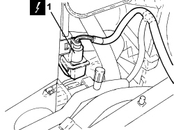
1. Disconnect the electrical connection for the turbo variable geometry control solenoid.
| Description | Connector | |
|---|---|---|
| 1 | Turbine variable geometry control solenoid | See L036 TURBINE VARIABLE GEOMETRY CONTROL SOLENOID VALVE |
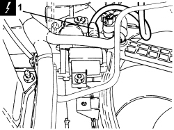
1. Disconnect the electrical connection for the air flow meter.
| Description | Connector | |
|---|---|---|
| 1 | Air flow meter | See K041 AIR FLOW METER |
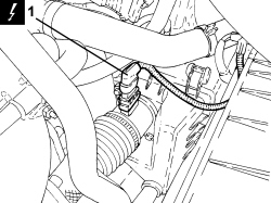
1. Disconnect the electrical connection for the engine coolant temperature sensor.
| Description | Connector | |
|---|---|---|
| 1 | Engine coolant temperature sensor/sender unit | See K036 ENGINE COOLANT TEMPERATURE SENSOR/SENDER UNIT |
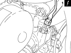
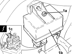
1. Undo nut (1a), remove glow heater plug preheating control unit (1b) and disconnect electrical connection (1c).
| Description | Connector | |
|---|---|---|
| 1c | Glow plug preheating control unit | See M015 PLUG PREHEATING CONTROL UNIT |
Op. 1080C24 E.G.R. SYSTEM SOLENOID - R + R
Op. 1080D34 ENGINE OIL VAPOUR SEPARATOR - R + R
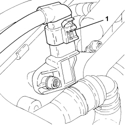
1. Detach the pressure relief sensor electrical connection.
| Description | Connector | |
|---|---|---|
| 1 | Air pressure - temperature sensor | See K044 AIR TEMPERATURE/PRESSURE SENSOR |
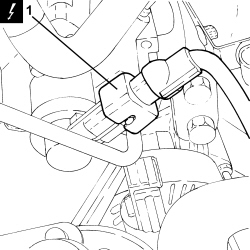
1. Detach the fuel pressure sensor electrical connection from the pressure pump.
| Description | Connector | |
|---|---|---|
| 1 | Fuel pressure regulator | See N077 FUEL PRESSURE REGULATOR |
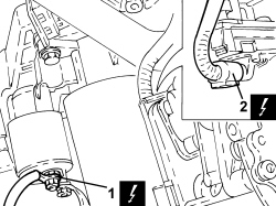
1. Open the protection, unscrew the nut and remove earth lead from the starter motor.
| Description | Connector | |
|---|---|---|
| 1 | Starter motor | See A020 STARTER MOTOR |
2. Detach the swirl actuator electrical connection.
| Description | Connector | |
|---|---|---|
| 2 | Flow modifier solenoid | See L064 FLOW MODIFYING SOLENOID VALVE |
1. Disconnect the electrical connection for the engine oil pressure warning light switch.
| Description | Connector | |
|---|---|---|
| 1 | Engine oil pressure sensor (switch) | See K030 ENGINE OIL PRESSURE SENSOR (SWITCH) |
2. Open the protection, unscrew the nut and disconnect the alternator earth lead.
| Description | Connector | |
|---|---|---|
| 2 | Alternator | See A010 ALTERNATOR |
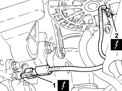
Op. 7055B54 UNDER ENGINE PROTECTION/GUARD - R.R.
1. Disconnect the electrical connection for the engine rpm sensor.
| Description | Connector | |
|---|---|---|
| 1 | Rpm sensor | See K046 RPM SENSOR |
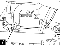
1. Detach the timing sensor electrical connection.
| Description | Connector | |
|---|---|---|
| 1 | Timing sensor | See K047 TIMING SENSOR |
2. Disconnect the electrical connection for the air conditioning compressor engagement electromagnet.
| Description | Connector | |
|---|---|---|
| 2 | Air conditioning compressor engagement electro-magnet | See L020 AIR CONDITIONING COMPRESSOR ENGAGEMENT ELECTRO-MAGNET |
3. Undo the nut and disconnect the air conditioning compressor earth lead.
| Description | Connector | |
|---|---|---|
| 3 | Compressor earth | See C039 COMPRESSOR EARTH |
4. Disconnect the electrical connections from the injectors and open the cable retaining clips.
| Description | Connector | |
|---|---|---|
| 4 | Injector | See N070 INJECTOR |
5. Detach the fuel pressure sensor electrical connection.
| Description | Connector | |
|---|---|---|
| 5 | Fuel pressure sensor | See K083 FUEL PRESSURE SENSOR |
6. Detach the electrical connections for the glow heater plugs.
| Description | Connector | |
|---|---|---|
| 6 | Glowheater plugs | See A040 HEATER PLUGS |
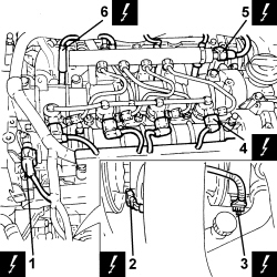
- Open the retaining clips and remove the wiring loom.
Refitting
- Fit the wiring loom in place and secure using the retaining clips.
- Connect the glowheater plug electrical connections.
- Connect the electrical connection for the fuel pressure sensor.
- Connect the electrical connections to the injectors and close the cable retaining clips.
- Connect the air conditioning compressor earth lead and tighten the nut.
- Connect the electrical connection for the air conditioning compressor engagement electromagnet.
- Secure the electrical connection for the timing sensor.
- Connect the electrical connection for the engine rpm sensor.
Op. 7055B54 UNDER ENGINE PROTECTION/GUARD - R.R.
- Connect the alternator earth lead, tighten the nut and close the protection.
- Connect the electrical connection for the engine oil pressure warning light switch.
- Connect the swirl actuator electrical connection.
- Connect the starter motor earth lead, tighten the nut and close the protection.
- Connect the fuel pressure sensor electrical connection on the pressure pump.
- Connect the electrical connection for the excess pressure sensor.
Op. 1080D34 ENGINE OIL VAPOUR SEPARATOR - R + R
Op. 1080C24 E.G.R. SYSTEM SOLENOID - R + R
- Connect the electrical connection, place the glow plug preheating control unit in position and secure by tightening the nut.
- Connect the engine coolant temperature sensor electrical connection.
- Connect the electrical connection for the flow meter.
- Connect the electrical connection for the turbo variable geometry control solenoid.
Op. 1048A21 FILTER AIR INTAKE HOSE - R.R.
Op. 5530B52 BATTERY SUPPORT/DRIP TRAY - R.R
Op. 1016A10 SOUND-PROOFING COVER - R.R
- Remove the vehicle from the lift.
Parts & tools for this job For 2007 Fiat Bravo
- PARTGlow plugsSearch: Fiat Bravo 2007 glow plugs
- TOOLGlow plug socketSearch: glow plug socket
- TOOLDiesel compression testerSearch: diesel compression tester
Links open Amazon search results in a new tab. As an Amazon Associate I earn from qualifying purchases.