
Differential assembly (page 4 of 5)
- Make
- Land Rover
- Model
- Discovery II (UK)
- Section
- Overhaul
Rear axleDifferential assembly · page 4 of 5
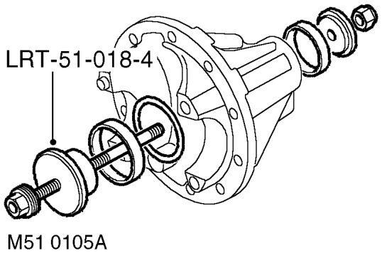
- Ensure original head bearing shim is clean and 19. Ensure pinion height setting block, setting free from burrs and fit under bearing race.
- Ensure pinion bearing cup recesses are clean and free of burrs and using LRT-51-018-4 fit 20. Locate setting block pinion head and tail bearing races.
- Fit pinion head bearing to pinion.
- Lubricate bearings with thin oil.
- Ensure original tail bearing shim is clean and free from burrs and fit under bearing race.
- Fit pinion and pinion tail bearing.
- Fit pinion flange, washer and bolt.
- Use LRT-51-003 to restrain pinion flange.
- Tighten pinion flange bolt to 100 Nm (74 lbf.ft).
- Check pinion for end float. Should read zero.
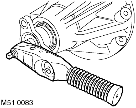
- Pinion height setting procedure:
- Rotate pinion several times to settle bearings, check pinion Torque to Turn. Torque to Turn should be recorded during pinion rotation. Pinion Torque to Turn should be 4 to 6 Nm (3 to 4.5 lbf.ft).
- Adjust size of tail bearing shim to obtain correct pinion Torque to Turn (0.025 mm = 1 Nm (0.001' = 0.7 lbf.ft) approximately).
- Position LRT-51-018-7 on surface plate, establish zero and reference DTI.
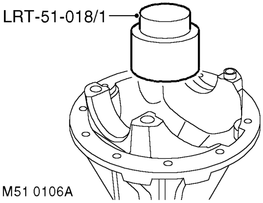
gauge and mating faces are clean and free from burrs. LRT-51-018/11 over pinion head, ensure it is fully seated in position.
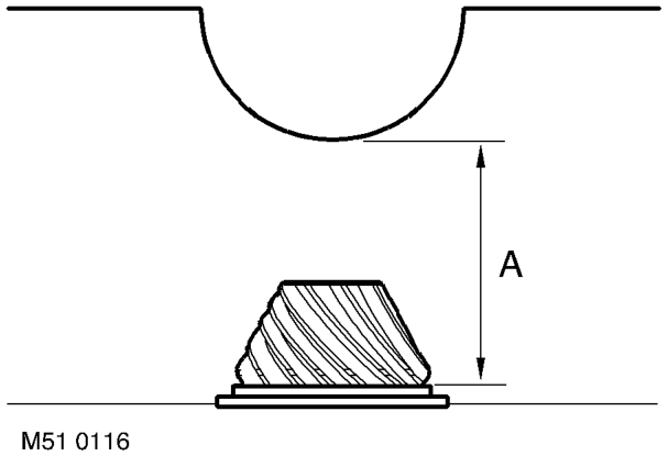
l 'A' = Nominal pinion height setting, 74.390. l 'B' = Setting block height. l 'C' = Head height setting. l 'C' = 'A' - 'B'. Subtract nominal pinion height 'A' from setting block height 'B' (on side of setting block). l Example: 74.390 - 73.130 = 1.26 mm (2.929' - 2.88' = 0.049'). Therefore pinion head height reading is 1.260 mm ± 0.025 mm (0.049' ± 0.001').
CAUTION: Setting block height must be checked using figures on side of block.
Parts & tools for this job For Land Rover Discovery
- PARTRear wheel bearingSearch: Land Rover Discovery rear wheel bearing
- TOOLBearing puller kitSearch: wheel bearing puller kit
- PARTCV boot kitSearch: Land Rover Discovery cv boot kit
Links open Amazon search results in a new tab. As an Amazon Associate I earn from qualifying purchases.