
RHD models only
- Make
- Rover
- Model
- 400 Workshop Manual
- Year
- 1995–2000
- Section
- Repairs › RHD models only
Engine management system - EDCRHD models only
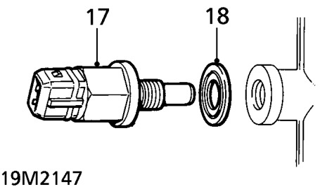
- Release throttle cable adjusting nut from abutment bracket.
- Disconnect throttle inner cable from throttle position sensor.
RHD models only
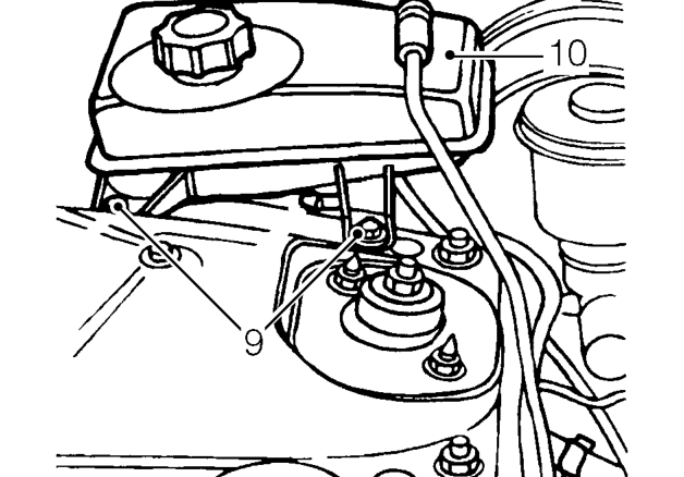
- Remove 2 bolts securing expansion tank to body.
- Release expansion tank from body and position aside.
All models
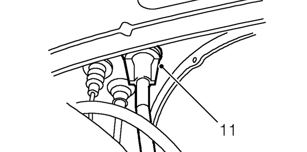
- Release cable from bulkhead.
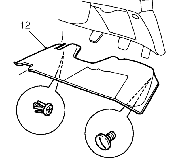
- Remove trim screw and scrivet securing closing panel in drivers footwell. Remove panel.
Parts & tools for this job For 1995 Rover 400
- PARTGlow plugsSearch: Rover 400 1995 glow plugs
- TOOLGlow plug socketSearch: glow plug socket
- TOOLDiesel compression testerSearch: diesel compression tester
Links open Amazon search results in a new tab. As an Amazon Associate I earn from qualifying purchases.