
Clearance
- Make
- Rover
- Model
- 600 Rover 600 Repair Manual - Volumes 1 and 2 - 2nd Edition
- Section
- Cylinder block: repairs › Clearance
Clearance
- Remove the connecting rod cap and bearing half.
- Clean the crankshaft rod journal and bearing half with a clean cloth.
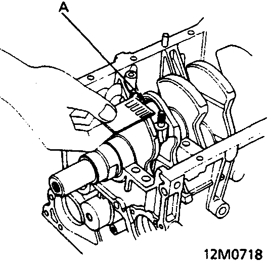
A Plastigage Strip
- Place the plastigage across the rod journal.
- Reinstall the bearing half and cap, and torque the nuts to 32Nm.
Note: Do not rotate the crankshaft during inspection.
- Remove the rod cap and bearing half and measure the widest part of the plastigage.
Connecting Rod Bearings – to – Journal Oil Clearance:
Standard (New): 0.015 – 0.043 mm
Service Limit: 0.050 mm
- If the plastigage measures too wide or too narrow, remove the upper half of the bearing, install a new, complete bearing with the same colour code and recheck the clearance.
CAUTION: Do not file, shim, or scrape the bearings or the caps to adjust clearance.
- If the plastigage shows the clearance is still incorrect, try the next larger or smaller bearing (the next colour listed above or below), and check clearance again.
Note: If the correct clearance cannot be obtained by using the appropriate larger or smaller bearings, replace the crankcase and repeat the checking procedure.
Selection
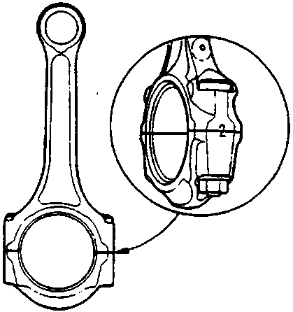
Connecting Rod Journal Code Location
(Numbers or Bars)
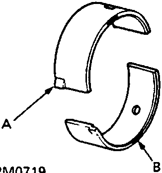
A Projection
B Colour
CAUTION: If the codes are indecipherable because of an accumulation of dirt and dust, do not scrub them with a wire brush or scraper. Clean them only with solvent or detergent.
Numbers or Bars have been stamped on the side of each connecting rod as a code for the size of the big end, with half the number or the bar stamped on the bearing cap and the other half on the rod. Use it, and the letters or bars stamped on the crankshaft (codes for rod journal size), to choose the correct bearings.
| 1 or I | 2 or ii | 3 or iil | 4 or iiil | |
|---|---|---|---|---|
| A or I | Red | Pink | Yellow | Green |
| B or ii | Pink | Yellow | Green | Brown |
| C or iil | Yellow | Green | Brown | Black |
| D or iiil | Green | Brown | Black | Blue |
Parts & tools for this job For Rover 600
- PARTEngine gasket setSearch: Rover 600 engine gasket set
- TOOLTorque wrenchSearch: 3/8 inch torque wrench
- TOOLFeeler gauge setSearch: feeler gauge set
Links open Amazon search results in a new tab. As an Amazon Associate I earn from qualifying purchases.