
Installation
- Make
- Rover
- Model
- 600 Rover 600 Repair Manual - Volumes 1 and 2 - 2nd Edition
- Section
- Cylinder block: repairs › Installation
Installation
Before installing the crankshaft, apply a coat of engine oil to the main bearings, rod bearings and balancer shaft bearings.
- Insert bearing halves in the cylinder block and connecting rods.
- Hold the crankshaft so rod journals for cylinders No. 2 and No. 3 are straight up.
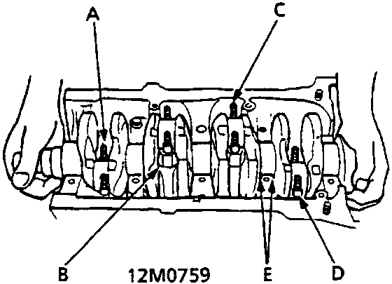
- Connecting Rod No. 1
- Connecting Rod No. 2
- Connecting Rod No. 3
- Connecting Rod No. 4
- Thrust Washers
- Lower the crankshaft into the block, seating the rod journals into connecting rods No. 1 and No. 4. Install the rod caps and nuts finger tight.
- Rotate the crankshaft clockwise, seat journals into connecting rods No. 2 and No. 3, and install the rod caps and nuts finger tight.
Note: Install caps so the bearing recess is on the same side as the recess in the rod.
- Check rod bearing clearance with plastigage then torque the capnuts to 32Nm.
Note: Reference numbers on connecting rod are for big - end bore tolerance and do not indicate the position of piston in the engine.
- Install the thrust washers (with grooved sides facing outward), main bearing caps and bearing cap bridge.
Note: Thrust washer thickness is fixed and must not be changed by grinding or shimming.
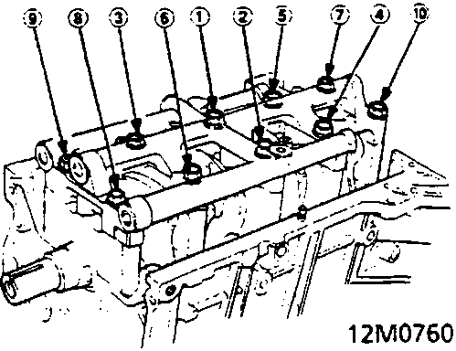
Check clearance with plastigage then tighten the bearing cap bolts in 2 steps.
In the first step tighten all bolts in the sequence shown, to 30 Nm; in the final step tighten in same sequence, to 75 Nm.
Note: Coat the bolt threads with engine oil.
CAUTION: Whenever any crankshaft or connecting rod bearing is replaced, it is necessary after reassembly to run the engine at idling speed until it reaches normal operating temperature, then continue to run it for approximately 15 minutes.
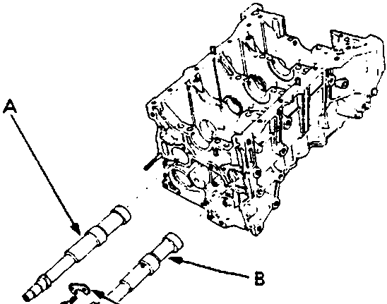
- Rear Balancer Shaft
- Front Balancer Shaft
- Retainer
20 N m
- Insert the balancer shafts into the block, then install the retainer to the front balancer shaft and block.
Parts & tools for this job For Rover 600
- PARTEngine gasket setSearch: Rover 600 engine gasket set
- TOOLTorque wrenchSearch: 3/8 inch torque wrench
- TOOLFeeler gauge setSearch: feeler gauge set
Links open Amazon search results in a new tab. As an Amazon Associate I earn from qualifying purchases.