Workshop Manuals Factory service & repair Rover
01 Information02 General data03 Engine04 Engine management system – PGM-Fi05 Cooling system, manifold and exhaust06 Clutch07 Manual gearbox08 Automatic gearbox09 Drive shafts10 Differential – manual gearbox11 Differential – automatic gearbox12 Steering13 Suspension14 Brakes and ABS15 Brakes – ABS BY416 Body17 Heating and ventilation18 Electrical19 Supplementary restraint system (SRS)
Rover Rover 600 Repair Manual - Volumes 1 and 2 - 2nd Edition03 · Engine
03 · Engine

Cylinder block

Make
Rover
Model
600 Rover 600 Repair Manual - Volumes 1 and 2 - 2nd Edition
Section
Cylinder block: repairs › Cylinder block
EngineCylinder block · page 1 of 3
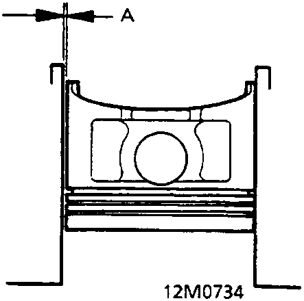
Cross-section diagram of a piston inside a cylinder showing the clearance gap at the top, labeled A.
A Piston – to – Cylinder Clearance 3. Calculate the difference between cylinder bore diameter and piston diameter. **Piston – to – Cylinder Clearance:** Standard (New): 0.020 – 0.040 mm Service Limit: 0.05 mm If the clearance is near or exceeds the service limit, inspect the piston and cylinder block for excessive wear. **Oversize Piston Diameter:** 0.25: 85.230 – 85.240 mm 0.50: 85.480 – 85.490 mm 4. Check the gudgeon pin – to – piston clearance. Coat the gudgeon pin with engine oil. It should then be possible to push the gudgeon pin into the piston hole with thumb pressure. **Gudgeon Pin – to Piston Clearance:** Standard (New): 0.012 – 0.024 mm

CYLINDER BLOCK

Inspection

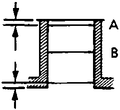
Diagram showing measurement points A, B, and C on a cylinder wall, with 6 mm spacing indicated from the top and bottom edges.
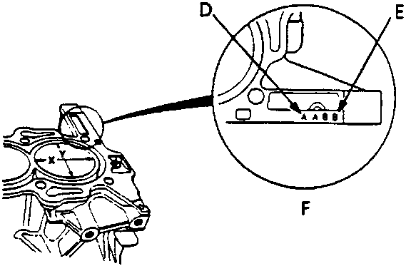
Diagram of an engine block with a magnified circular inset showing the locations of cylinders No. 1 (D) and No. 4 (E) and their respective bore size letters.
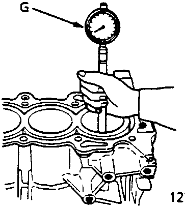
Diagram showing a hand using a cylinder bore gauge to measure the interior of a cylinder in the engine block.
A First measurement B Second measurement C Third measurement D No. 1 E No. 4 F Cylinder Bore Sizes G Cylinder Bore Gauge 1. Measure wear and taper in direction X and Y at three levels in each cylinder as shown. Note: The cylinder bore size letters (A or I, B or II) are stamped on the block, No. 1 cylinder on the left through to No. 4 cylinder on the right.

Parts & tools for this job For Rover 600

Links open Amazon search results in a new tab. As an Amazon Associate I earn from qualifying purchases.