
Original page
- Make
- Rover
- Model
- 600 Rover 600 Repair Manual - Volumes 1 and 2 - 2nd Edition
- Section
- Cylinder block: repairs › Original page
EngineOriginal page
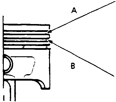
A
Top RingB
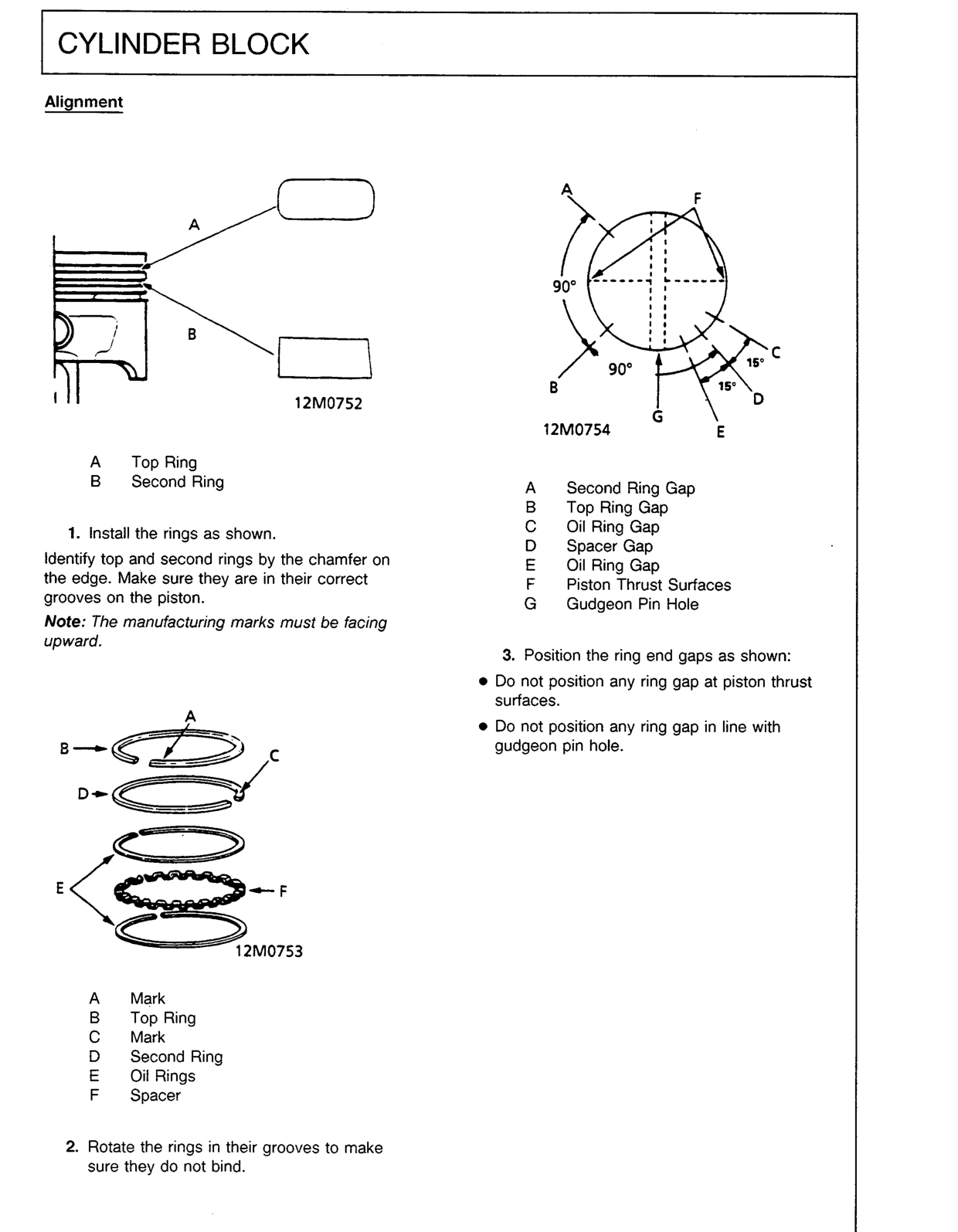
Second Ring- Install the rings as shown.
Identify top and second rings by the chamfer on the edge. Make sure they are in their correct grooves on the piston.
Note: The manufacturing marks must be facing upward.
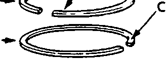
- Rotate the rings in their grooves to make sure they do not bind.
A
MarkB
Top RingC
MarkD
Second RingE
Oil RingsF
Spacer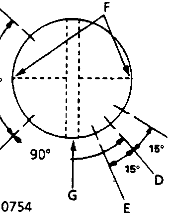
A
Second Ring GapB
Top Ring GapC
Oil Ring GapD
Spacer GapE
Oil Ring GapF
Piston Thrust SurfacesG
Gudgeon Pin Hole- Position the ring end gaps as shown:
- Do not position any ring gap at piston thrust surfaces.
- Do not position any ring gap in line with gudgeon pin hole.
Original page
Parts & tools for this job For Rover 600
- PARTEngine gasket setSearch: Rover 600 engine gasket set
- TOOLTorque wrenchSearch: 3/8 inch torque wrench
- TOOLFeeler gauge setSearch: feeler gauge set
Links open Amazon search results in a new tab. As an Amazon Associate I earn from qualifying purchases.