
Crankshaft
- Make
- Rover
- Model
- 600 Rover 600 Repair Manual - Volumes 1 and 2 - 2nd Edition
- Section
- Cylinder block: repairs › Crankshaft
EngineCrankshaft
Note: The existing number on the connecting rod does not indicate its position in the engine, it indicates the rod bore size.
CRANKSHAFT
Inspection
- Clean the crankshaft oil passages with pipe cleaners or a suitable brush.
- Check the keyway and threads.
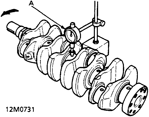
- A Dial Indicator
Alignment
- Support crankshaft with a lathe – type tool or V – blocks and, using a dial indicator, measure runout on all main journals to make sure the crankshaft is not bent. When making measurements rotate crankshaft two complete revolutions in the direction shown.
- The difference between measurements on each journal must not be more than the service limit.
Crankshaft Total Indicated Runout:
Standard (New): 0.03 mm
Service Limit: 0.04 mm
Parts & tools for this job For Rover 600
- PARTEngine gasket setSearch: Rover 600 engine gasket set
- TOOLTorque wrenchSearch: 3/8 inch torque wrench
- TOOLFeeler gauge setSearch: feeler gauge set
Links open Amazon search results in a new tab. As an Amazon Associate I earn from qualifying purchases.