
Crankshaft, balancer shafts and pistons (page 3 of 3)
- Make
- Rover
- Model
- 600 Rover 600 Repair Manual - Volumes 1 and 2 - 2nd Edition
- Section
- Cylinder block: repairs
EngineCrankshaft, balancer shafts and pistons · page 3 of 3
bolts in sequence 1/3 turn at a time; repeat the sequence until all bolts are loosened.
- Turn the crankshaft so No. 2 and 3 crankpins are at the top.
- Remove the rod caps/bearings and main caps/bearings. Keep all caps/bearings in order.
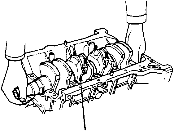
- A Crankshaft
- Lift the crankshaft out of the engine, being careful not to damage journals.
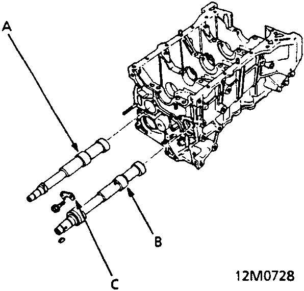
- A Rear Balancer Shaft
- B Front Balancer Shaft
- C Retainer
- Remove the bolts and the retainer, then remove the front balancer shaft and the rear balancer shaft.
- Remove the upper bearing halves from the connecting rods and set them aside with their respective caps.
- Reinstall the main caps and bearings on the engine in the correct order.
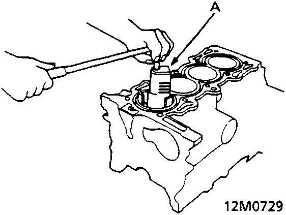
- A Ridge Reamer
- If you can feel a ridge of metal or hard carbon around the top of each cylinder, remove it with a ridge reamer. Follow the reamer manufacturer's instructions.
CAUTION: If the ridge is not removed, it may damage the pistons as they are pushed out.
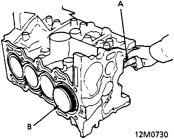
- A Hammer Handle
- B Piston
- Use the wooden handle of a hammer to drive the pistons out.
- Reinstall the connecting rod bearings and caps after removing each piston/connecting rod assembly.
- Mark each piston/connecting rod assembly with its cylinder number to avoid mixup on reassembly.
Parts & tools for this job For Rover 600
- PARTEngine gasket setSearch: Rover 600 engine gasket set
- TOOLTorque wrenchSearch: 3/8 inch torque wrench
- TOOLFeeler gauge setSearch: feeler gauge set
Links open Amazon search results in a new tab. As an Amazon Associate I earn from qualifying purchases.