
Replacement
- Make
- Rover
- Model
- 600 Rover 600 Repair Manual - Volumes 1 and 2 - 2nd Edition
- Section
- Cylinder block: repairs › Replacement
EngineReplacement · page 1 of 7
Replacement
The following procedure is used when using the bearing replacement tool set 18G1698.
CAUTION:
- Remove all attachments from the cylinder block and lay it with its sump side up.
- Remove or reinstall bearings one at a time.
- Remove bearings from the transmission side to the timing belt side and reinstall them in reverse sequence.
Special Tool Set Location
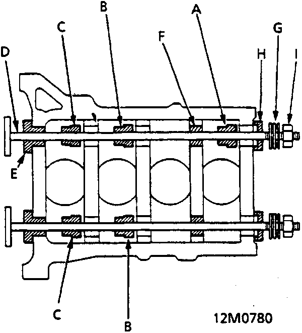
- A Attachment A
- B Attachment B
- C Attachment C
- D Shaft
- E Guide
- F Guide
- G Thrust Bearing
- H Base
- I Nut
- By changing the size and attachment point of the attachment, all balancer bearings can be removed from the cylinder block in the same procedure.
- The illustration shows the attachment points of each special tool.
- When removing bearings successively, put the corresponding attachment through the shaft without fixing them in advance.
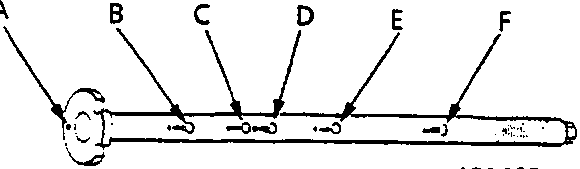
- A A - Install
- B C - Remove
- C B - Install
- D B - Remove
- E C - Install
- F A - Remove
- Position of attachment fixing holes and guide marks on the shaft.
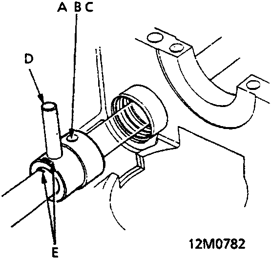
- A Front No. 1 Bearing: Attachment A
- B No. 2 Bearings: Attachment B
- C No. 3 Bearings: Attachment C
- D Stopper Pin
- E Guide Mark
- Put the attachment with the side having larger diameter facing the bearing. Align the stopper pin holes of the attachment and the shaft. Insert the stopper pin to fix the attachment.
Parts & tools for this job For Rover 600
- PARTEngine gasket setSearch: Rover 600 engine gasket set
- TOOLTorque wrenchSearch: 3/8 inch torque wrench
- TOOLFeeler gauge setSearch: feeler gauge set
Links open Amazon search results in a new tab. As an Amazon Associate I earn from qualifying purchases.