
Replacement (page 5 of 7)
- Make
- Rover
- Model
- 600 Rover 600 Repair Manual - Volumes 1 and 2 - 2nd Edition
- Section
- Cylinder block: repairs
EngineReplacement · page 5 of 7
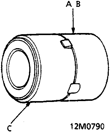
No. 2 and No. 3 Bearings
A No. 2 Bearings: Attachment B
B No. 3 Bearings: Attachment C
C Bearing
- Set the recess of the bearing to the detent of the attachment.
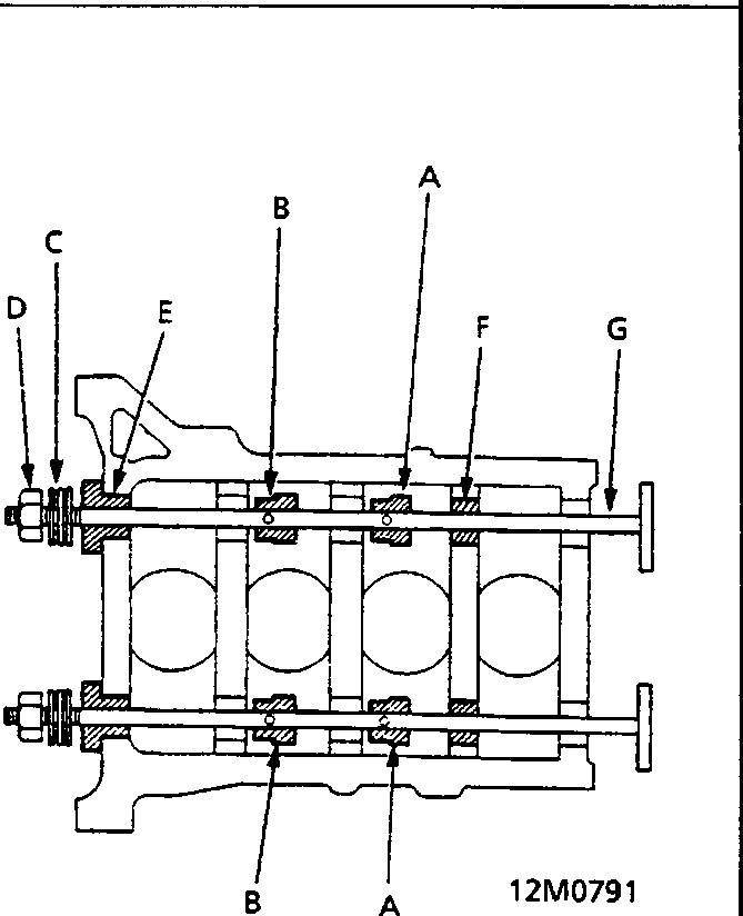
A Attachment B
B Attachment C
C Thrust Bearing
D Nut
E Guide
F Guide
G Shaft
- The illustration shows attachment points of each special tool.
- When installing bearings successively, set the bearings to the attachment and put them through the shaft without fixing them in advance.
Parts & tools for this job For Rover 600
- PARTEngine gasket setSearch: Rover 600 engine gasket set
- TOOLTorque wrenchSearch: 3/8 inch torque wrench
- TOOLFeeler gauge setSearch: feeler gauge set
Links open Amazon search results in a new tab. As an Amazon Associate I earn from qualifying purchases.