
Installation
- Make
- Rover
- Model
- 600 Rover 600 Repair Manual - Volumes 1 and 2 - 2nd Edition
- Section
- Cylinder block: repairs › Installation
EngineInstallation
Installation
Before installing the piston, apply a coat of engine oil to the ring grooves and cylinder bores.
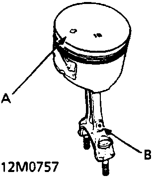
- A
- B
A Arrow
B Connecting Rod Oil Hole
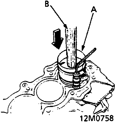
- A
- B
A Ring Compressor
B Wooden Handle
- If the crankshaft is already installed:
- Remove the connecting rod caps and slip short sections of rubber hose over the threaded ends of the connecting rod bolts.
- Install the ring compressor, check that the bearing is securely in place, then position the piston in the cylinder with the arrow on the piston crown facing the timing belt side of the engine and the connecting rod oil hole facing the intake manifold and tap it in using the wooden handle of a hammer.
- Stop after the ring compressor pops free and check the connecting rod - to - crank journal alignment before pushing piston into place.
- Install the rod caps with bearings, and torque the nuts to 47Nm.
- If the crankshaft is not installed:
- Remove the rod caps and bearings, install the ring compressor, then position the piston in the cylinder with the arrow on the piston crown facing the timing belt of the engine and the connecting rod oil hole facing the intake manifold and tap it in using the wooden handle of a hammer.
- Position all pistons at top dead centre.
Note: Maintain downward force on the ring compressor to prevent rings from expanding before entering the cylinder bore.
Parts & tools for this job For Rover 600
- PARTEngine gasket setSearch: Rover 600 engine gasket set
- TOOLTorque wrenchSearch: 3/8 inch torque wrench
- TOOLFeeler gauge setSearch: feeler gauge set
Links open Amazon search results in a new tab. As an Amazon Associate I earn from qualifying purchases.