
Replacement (page 6 of 7)
- Make
- Rover
- Model
- 600 Rover 600 Repair Manual - Volumes 1 and 2 - 2nd Edition
- Section
- Cylinder block: repairs
EngineReplacement · page 6 of 7
F1
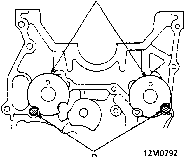
- Front Side
- Rear Side
- End Disk
- Positioning Pin
- Install the shaft positioning pin.
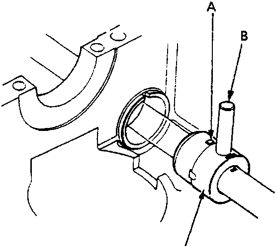
- Bearing
- Stopper Pin
- Attachment
- Align the attachment with the guide mark. Applicable bearing No. is indicated at the guide mark. Align the pin holes of the attachment and the shaft. Insert the stopper pin to fix the attachment (for No. 2, and No. 3 bearings).
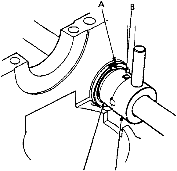
- Groove
- Detent
- Bearing
- Attachment
- Set the detent of the bearing to the groove of the cylinder block.
Parts & tools for this job For Rover 600
- PARTEngine gasket setSearch: Rover 600 engine gasket set
- TOOLTorque wrenchSearch: 3/8 inch torque wrench
- TOOLFeeler gauge setSearch: feeler gauge set
Links open Amazon search results in a new tab. As an Amazon Associate I earn from qualifying purchases.