
Connecting rods (page 2 of 2)
- Make
- Rover
- Model
- 600 Rover 600 Repair Manual - Volumes 1 and 2 - 2nd Edition
- Section
- Cylinder block: repairs
EngineConnecting rods · page 2 of 2
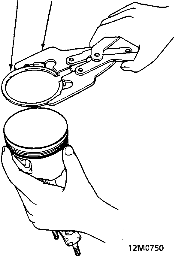
A Piston Ring
B Ring Expander
- Using a ring expander, remove the old piston rings.
- Clean all ring grooves thoroughly.
Note:
- Use a squared - off broken ring or ring groove cleaner with blade to fit piston grooves.
- Top and 2nd ring grooves are 1.2 mm wide and the oil ring groove is 2.8 mm wide.
- File down blade if necessary.
- If the piston is to be separated from the connecting rod, do not install new rings yet.
CAUTION: Do not use a wire brush to clean the ring grooves, or cut ring grooves deeper with cleaning tools.
- Install new rings in the correct sequence and position.
Note: Do not use old piston rings.
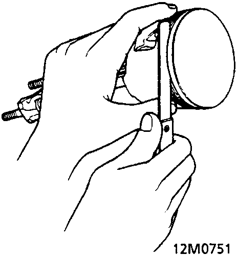
After installing a new set of rings, measure the ring - to - groove clearances:
Top Ring Clearance
Standard (New): 0.035 ÷ 0.060 mm
Service Limit: 0.13 mm
Second Ring Clearance
Standard (New): 0.030 ÷ 0.055 mm
Service Limit: 0.13 mm
Parts & tools for this job For Rover 600
- PARTEngine gasket setSearch: Rover 600 engine gasket set
- TOOLTorque wrenchSearch: 3/8 inch torque wrench
- TOOLFeeler gauge setSearch: feeler gauge set
Links open Amazon search results in a new tab. As an Amazon Associate I earn from qualifying purchases.