
Refit (page 3 of 3)
- Make
- Rover
- Model
- 600 Rover 600 Repair Manual - Volumes 1 and 2 - 2nd Edition
- Section
- Repairs
Engine management system – PGM-FiRefit · page 3 of 3
Refit (page 3 of 3) – diagram from the Engine management system – PGM-Fi chapter of the Rover Rover 600 Repair Manual - Volumes 1 and 2 - 2nd Edition factory manual.
- Use new gaskets when installing the intake manifold.
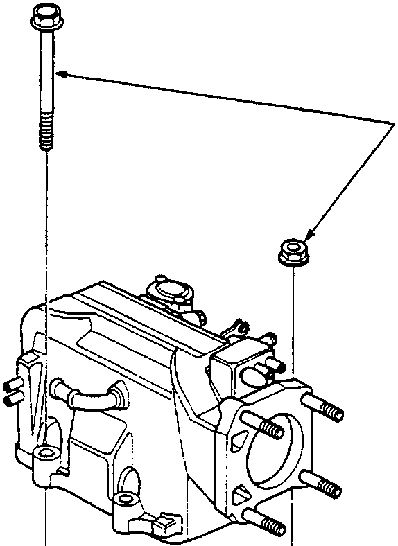
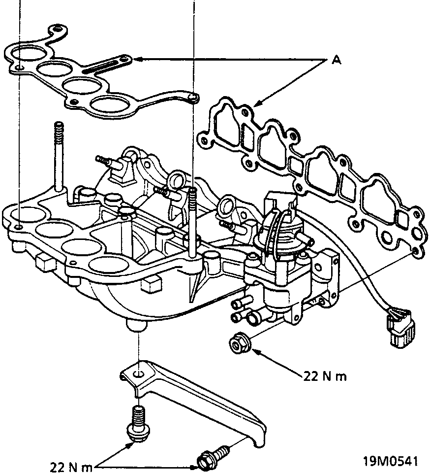
A Gasket
Parts & tools for this job For Rover 600
- PARTEngine gasket setSearch: Rover 600 engine gasket set
- TOOLTorque wrenchSearch: 3/8 inch torque wrench
- TOOLFeeler gauge setSearch: feeler gauge set
Links open Amazon search results in a new tab. As an Amazon Associate I earn from qualifying purchases.