
Clutch Inspection (page 4 of 4)
- Make
- Rover
- Model
- 600 Rover 600 Repair Manual - Volumes 1 and 2 - 2nd Edition
- Section
- Repairs
Heating and ventilationClutch Inspection · page 4 of 4
Note: Make sure the suction and discharge ports are plugged with caps.
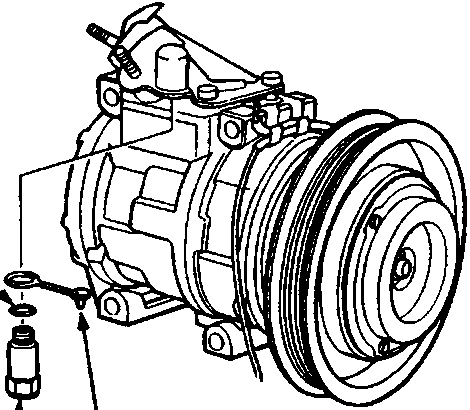
80M0115
- A Relief valve cap
- B Relief valve
- C 'O' ring
- Remove the relief valve and the 'O' ring.
CAUTION:
- Do not disassemble the compressor.
- Do not let the compressor oil run out.
- Make sure there is no foreign matter in the system.
- Install and tighten the relief valve.
- Clean all mating surfaces.
- Replace the 'O' ring with a new one at the relief valve and apply a thin coat of refrigerant oil (Nippondenso Densoil 8) prior to installation.
Note:
- To avoid contamination, once dispensed do not return the oil to the container and never mix with other refrigerant oils.
- Replace the cap on the container immediately after use and seal it to avoid moisture absorption.
- Do not spill the refrigerant on the car; it may damage the paint; if the refrigerant oil contacts the paint, wash it off immediately.
- Check for leaks and insert the cap in the top of the valve.
Parts & tools for this job For Rover 600
- PARTClutch kitSearch: Rover 600 clutch kit
- TOOLClutch alignment toolSearch: clutch alignment tool
- FLUIDGear oilSearch: Rover 600 manual gearbox oil
Links open Amazon search results in a new tab. As an Amazon Associate I earn from qualifying purchases.