
Engine and manual gearbox (page 3 of 9)
- Make
- Rover
- Model
- 600 620 Diesel Repair Manual Supplement
- Year
- 1995–1999
- Section
- Repairs
EngineEngine and manual gearbox · page 3 of 9
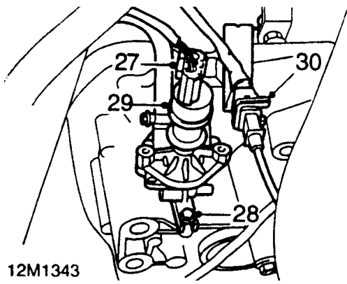
- Disconnect multiplug from speed sensor.
- Remove bolt securing power steering speed sensor to gearbox.
- Release speed sensor from gearbox and position aside.
- Release crankshaft sensor connector from bracket and disconnect multiplug.
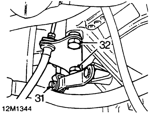
- Remove ’R’ clip securing clutch slave cylinder push rod to release lever, remove washer, clevis pin and push rod.
- Remove 2 bolts securing slave cylinder mounting bracket to gearbox and position aside.
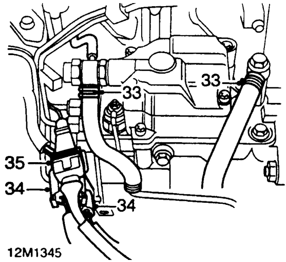
- Release clips and disconnect 2 fuel hoses from fuel injection pump.
- Disconnect 2 fuel injection pump multiplugs.
- Disconnect No.1 injector needle lift sensor multiplug.
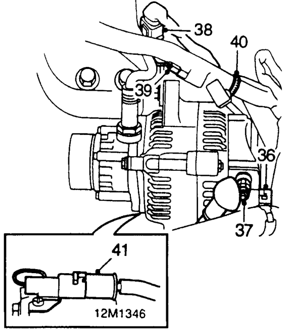
- Disconnect alternator multiplug.
- Remove nut securing alternator lead.
- Disconnect coolant temperature sensor multiplug.
- Disconnect coolant temperature gauge sensor connector.
- Release engine harness clip from dipstick tube bracket.
- Disconnect air conditioning compressor multiplug.
Parts & tools for this job For 1995 Rover 600
- PARTEngine gasket setSearch: Rover 600 1995 engine gasket set
- TOOLTorque wrenchSearch: 3/8 inch torque wrench
- TOOLFeeler gauge setSearch: feeler gauge set
Links open Amazon search results in a new tab. As an Amazon Associate I earn from qualifying purchases.