
Engine and manual gearbox (page 5 of 9)
- Make
- Rover
- Model
- 600 620 Diesel Repair Manual Supplement
- Year
- 1995–1999
- Section
- Repairs
EngineEngine and manual gearbox · page 5 of 9
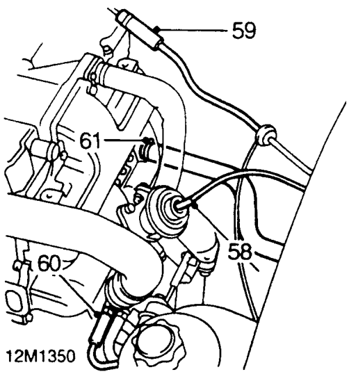
- Disconnect vacuum hose from EGR valve.
- Release clip and disconnect vacuum hose from vacuum pump pipe.
- Disconnect boost pressure sensing pipe from turbocharger.
- Slacken clip and disconnect coolant heater feed hose from engine outlet pipe.
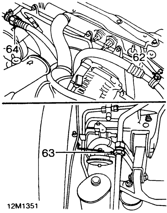
- Remove bolt securing air conditioning suction pipe clip to bonnet locking panel.
- Slacken air conditioning suction pipe union, remove and discard ’O’ ring seal.
- Slacken air conditioning pressure pipe union, remove and discard ’O’ ring seal.
NOTE: Plug or cap the lines immediately after disconnecting to avoid moisture and dust contamination entering into the system.
CAUTION: Use 2 spanners when loosening or tightening unions.
Parts & tools for this job For 1995 Rover 600
- PARTEngine gasket setSearch: Rover 600 1995 engine gasket set
- TOOLTorque wrenchSearch: 3/8 inch torque wrench
- TOOLFeeler gauge setSearch: feeler gauge set
Links open Amazon search results in a new tab. As an Amazon Associate I earn from qualifying purchases.