
Air flow sensor
- Make
- Rover
- Model
- 600 620 Diesel Repair Manual Supplement
- Year
- 1995–1999
- Section
- Repairs › Air flow sensor
Engine management systemAir flow sensor
AIR FLOW SENSOR
Service repair no - 19.22.25
Remove
- Disconnect battery earth lead.
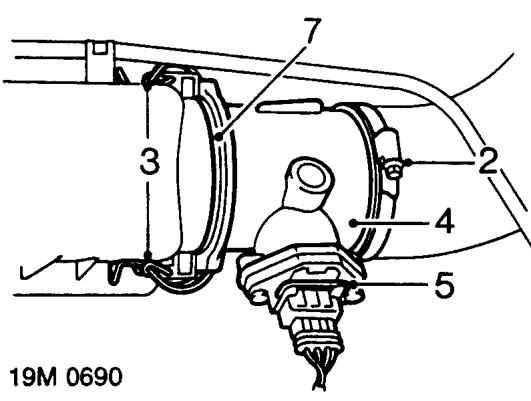
- Slacken clip securing air intake hose to air flow sensor, disconnect hose.
- Release 2 clips securing air flow sensor to air cleaner.
- Release air flow sensor from air cleaner.
- Release clip and disconnect multiplug.
- Remove air flow sensor.
- Remove and discard ’O’ ring.
Refit
- Fit new ’O’ ring to air flow sensor.
- Connect multiplug.
- Fit air flow sensor to air cleaner.
- Secure clips.
- Connect intake hose to air flow sensor, tighten clip.
- Connect battery earth lead.
AIR INTAKE HOSE
Service repair no - 19.42.28
Remove
- Disconnect battery earth lead.
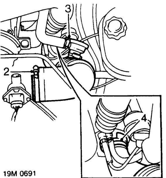
- Slacken clip and disconnect hose from air flow sensor.
- Slacken clip and disconnect one-way valve from air intake hose.
- Slacken clip securing air intake hose to turbocharger, remove air intake hose.
Refit
- Connect air intake hose to turbocharger and tighten clip.
- Connect one-way valve to intake hose and tighten clip.
- Connect air intake hose to air flow sensor and tighten clip.
- Connect battery earth lead.
Parts & tools for this job For 1995 Rover 600
- TOOLOBD2 scannerSearch: OBD2 scanner
- TOOLDigital multimeterSearch: automotive digital multimeter
- TOOLBack-probe test leadsSearch: back probe test leads
Links open Amazon search results in a new tab. As an Amazon Associate I earn from qualifying purchases.