
Injector needle lift sensor
- Make
- Rover
- Model
- 600 620 Diesel Repair Manual Supplement
- Year
- 1995–1999
- Section
- Repairs › Injector needle lift sensor
Engine management systemInjector needle lift sensor · page 1 of 2
INJECTOR NEEDLE LIFT SENSOR
Service repair no - 18.30.72
NOTE: The injector needle lift sensor is an integral part of No. 1 injector and cannot be replaced seperately.
Remove
- Disconnect battery earth lead.
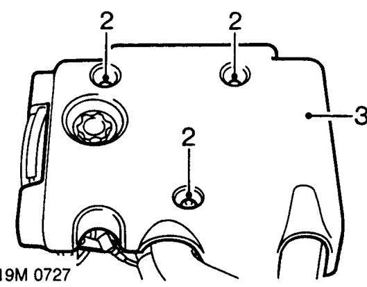
- Remove 3 bolts securing sound deadening pad to engine.
- Remove sound deadening pad.
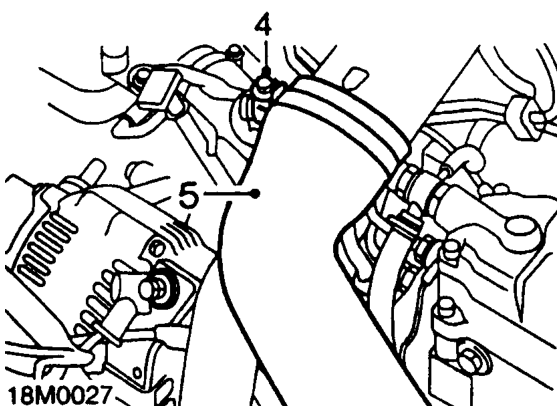
- Slacken clip and disconnect intercooler top hose from inlet manifold.
- Position hose aside.
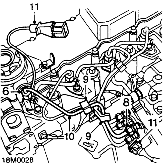
- Slacken injector pipe union at injector.
- Position absorbent cloth around fuel injection pump connection to catch fuel spillage.
- Slacken injector pipe union at injection pump.
CAUTION: To prevent damage to fuel system pipes or components, use 2 spanners when loosening or tightening unions.
- Release 2 clips securing injector pipes together.
- Disconnect injector pipe unions from fuel injection pump and injector, remove injector pipe.
CAUTION: Plug the connections to prevent the ingress of dirt.
- Disconnect injector needle lift sensor multiplug from harness.
Parts & tools for this job For 1995 Rover 600
- TOOLOBD2 scannerSearch: OBD2 scanner
- TOOLDigital multimeterSearch: automotive digital multimeter
- TOOLBack-probe test leadsSearch: back probe test leads
Links open Amazon search results in a new tab. As an Amazon Associate I earn from qualifying purchases.