
Injector needle lift sensor (page 2 of 2)
- Make
- Rover
- Model
- 600 620 Diesel Repair Manual Supplement
- Year
- 1995–1999
- Section
- Repairs
Engine management systemInjector needle lift sensor · page 2 of 2
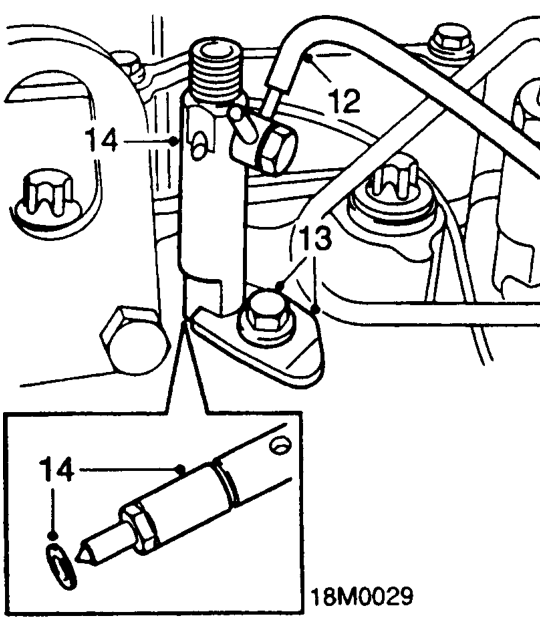
- Disconnect spill return pipe from injector.
- Remove bolt and collect clamp plate securing injector to cylinder head.
- Remove injector from cylinder head, remove and discard sealing washer. Do not carry out further dismantling if component is removed for access only.
- Remove spill return pipe banjo bolt and discard 2 sealing washer.
- Using new sealing washers, fit spill return pipe to new injector and tighten banjo bolt.
Refit
- Thoroughly clean injector and injector seat in cylinder head.
- Fit new sealing washer to injector and fit injector to cylinder head.
CAUTION: Domed surface of sealing washer must face towards injector.
- Fit clamp plate to injector, align injector and clamp plate to bolt hole in cylinder head.
- Fit injector clamp plate bolt and tighten to 23 Nm.
- Connect spill return pipe to injector.
- Connect needle lift sensor multiplug to harness.
- Remove plugs from injector pipe, injection pump and injector unions.
- Clean injector pipe, injection pump and injector unions.
- Position injector pipe to injection pump and injector, connect unions.
- Align injector pipe to other injector pipes, fit and secure retaining clips.
- Tighten injector pipe to injector union to 28 Nm.
- Tighten injector pipe to injection pump union to 28 Nm.
CAUTION: To prevent damage to fuel system pipes or components, use 2 spanners when loosening or tightening unions.
- Connect intercooler top hose to inlet manifold and tighten clip.
- Position sound deadening pad and secure with bolts.
- Connect battery earth lead.
Parts & tools for this job For 1995 Rover 600
- TOOLOBD2 scannerSearch: OBD2 scanner
- TOOLDigital multimeterSearch: automotive digital multimeter
- TOOLBack-probe test leadsSearch: back probe test leads
Links open Amazon search results in a new tab. As an Amazon Associate I earn from qualifying purchases.