
Engine control module
- Make
- Rover
- Model
- 600 620 Diesel Repair Manual Supplement
- Year
- 1995–1999
- Section
- Repairs › Engine control module
Engine management systemEngine control module
ENGINE CONTROL MODULE
Service repair no - 18.30.01
Remove
- Disconnect both battery leads, earth lead first.
- Remove trim fastener securing passenger’s footwell carpet to centre console.
- Release passenger’s footwell carpet from base of ’A’ post, bulkhead and rear of centre console.
- Fold back passenger’s footwell carpet.
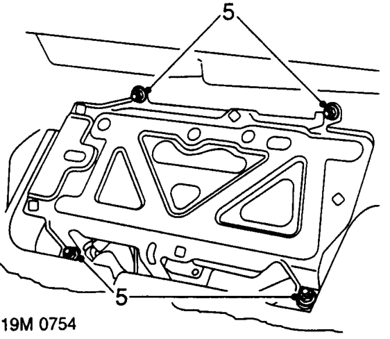
- Remove 4 nuts securing ECM mounting bracket to bulkhead.
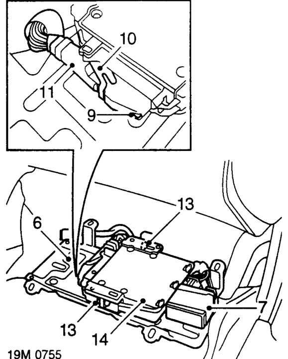
- Release mounting bracket from studs.
- Release clip and disconnect cooling fan relay module from mounting bracket.
- Manoeuvre mounting bracket to gain access to ECM multiplug.
- Remove screw securing multiplug to ECM.
- Release metal clip securing multiplug to ECM.
- Disconnect multiplug from ECM.
NOTE: Take care when disconnecting multiplug from ECM as it is possible to break the bridging piece which secures the multiplug to ECM.
- Remove ECM and mounting bracket.
- Remove 2 nuts securing ECM to mounting bracket.
- Remove ECM.
Parts & tools for this job For 1995 Rover 600
- TOOLOBD2 scannerSearch: OBD2 scanner
- TOOLDigital multimeterSearch: automotive digital multimeter
- TOOLBack-probe test leadsSearch: back probe test leads
Links open Amazon search results in a new tab. As an Amazon Associate I earn from qualifying purchases.