
Injectors
- Make
- Rover
- Model
- 600 620 Diesel Repair Manual Supplement
- Year
- 1995–1999
- Section
- Repairs › Injectors
Engine management systemInjectors
INJECTORS
Service repair no - 19.60.10
NOTE: No. 1 injector incorporates the needle lift sensor and is covered in a seperate procedure, see Needle lift sensor.
Remove
- Disconnect battery earth lead.
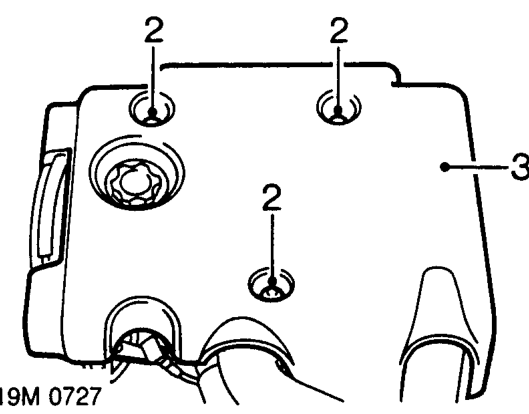
- Remove 3 bolts securing sound deadening pad to engine.
- Remove sound deadening pad.
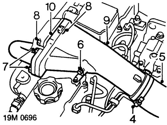
- Slacken clip and disconnect intercooler top hose from inlet manifold.
- Position hose aside.
No. 2 injector only
- Remove bolt securing inlet manifold intake pipe to camshaft cover bracket.
- Remove 2 bolts securing EGR recirculation pipe to inlet manifold intake pipe.
- Remove 2 bolts securing intake pipe to inlet manifold.
- Remove inlet manifold intake pipe.
- Remove and discard gasket.
Parts & tools for this job For 1995 Rover 600
- PARTFuel filterSearch: Rover 600 1995 fuel filter
- TOOLFuel pressure test kitSearch: fuel pressure test kit
- TOOLFuel line disconnect toolSearch: fuel line disconnect tool
Links open Amazon search results in a new tab. As an Amazon Associate I earn from qualifying purchases.