
Models with air conditioning
- Make
- Rover
- Model
- 600 620 Diesel Repair Manual Supplement
- Year
- 1995–1999
- Section
- Repairs › Models with air conditioning
Engine management systemModels with air conditioning · page 1 of 3
Refit
- Clean threads of coolant temperature sensor and apply Loctite 577.
- Fit coolant temperature and tighten to 5 Nm.
- Connect multiplug to coolant temperature sensor.
Models with air conditioning
- Position alternator top mounting bracket to coolant outlet elbow, fit bolts and tighten to 25 Nm.
- Check condition of the alternator drive belt. See MAINTENANCE.
- Hold tensioner pulley fully clockwise, using assistance fit drive belt around alternator pulley, ensure belt is correctly aligned in pulley grooves.
- Remove 15 mm ring spanner from tensioner pulley bolt.
All models
- Position sound deadening pad to engine and secure with bolts.
- Connect battery earth lead.
THROTTLE POSITION SENSOR
Service repair no - 19.22.49
Remove
- Disconnect battery earth lead.
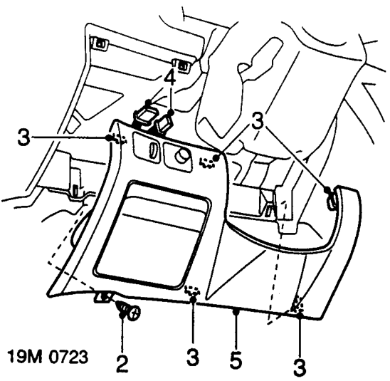
- Remove screw securing lower fascia closing panel to fascia.
- Release 5 clips securing lower fascia closing panel to fascia.
- Disconnect multiplug from instrument panel illumination switch. Models fitted with headlamp levelling: Disconnect multiplug from headlamp levelling switch.
- Remove lower fascia closing panel.
Parts & tools for this job For 1995 Rover 600
- TOOLA/C manifold gauge setSearch: AC manifold gauge set
- TOOLUV leak detection kitSearch: AC UV leak detection kit
- PARTCabin filterSearch: Rover 600 1995 cabin filter
Links open Amazon search results in a new tab. As an Amazon Associate I earn from qualifying purchases.