
Models with air conditioning (page 2 of 3)
- Make
- Rover
- Model
- 600 620 Diesel Repair Manual Supplement
- Year
- 1995–1999
- Section
- Repairs
Engine management systemModels with air conditioning · page 2 of 3
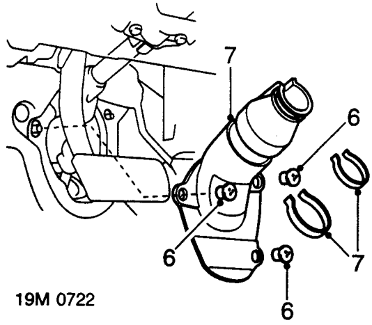
- Remove 3 trim fasteners securing universal joint cover to bulkhead.
- Release 2 clips securing universal joint cover to steering column and remove cover.
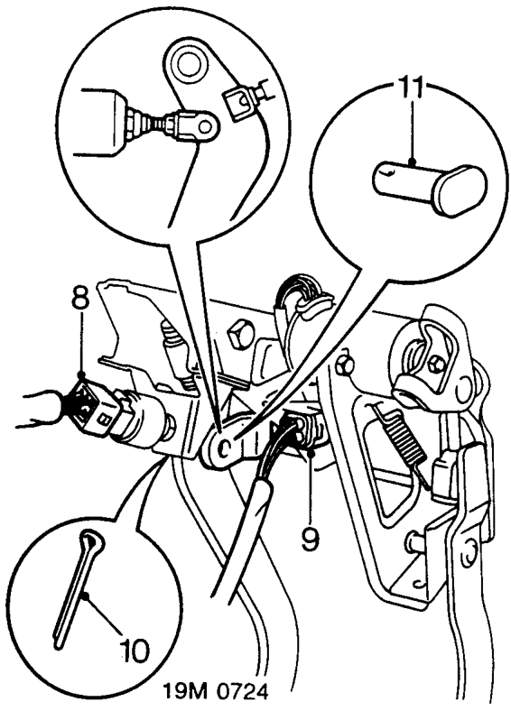
- Disconnect multiplug from brake pedal switch.
- Disconnect multiplug from throttle position sensor.
- Remove and discard split pin from servo push rod clevis pin.
- Remove servo push rod clevis pin.
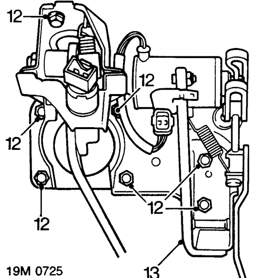
- Remove bolt and 6 nuts securing pedal box assembly to bulkhead and underside of fascia.
- Release pedal box assembly from studs on bulkhead and manoeuvre from beneath fascia.
CAUTION: Do not damage brake pedal switch.
Parts & tools for this job For 1995 Rover 600
- TOOLA/C manifold gauge setSearch: AC manifold gauge set
- TOOLUV leak detection kitSearch: AC UV leak detection kit
- PARTCabin filterSearch: Rover 600 1995 cabin filter
Links open Amazon search results in a new tab. As an Amazon Associate I earn from qualifying purchases.