
Braking system operation (Brakes)
- Make
- Rover
- Model
- 800 Workshop Manual
- Year
- 1996–1999
- Section
- Description and operation › Braking system operation
BRAKING SYSTEM OPERATION
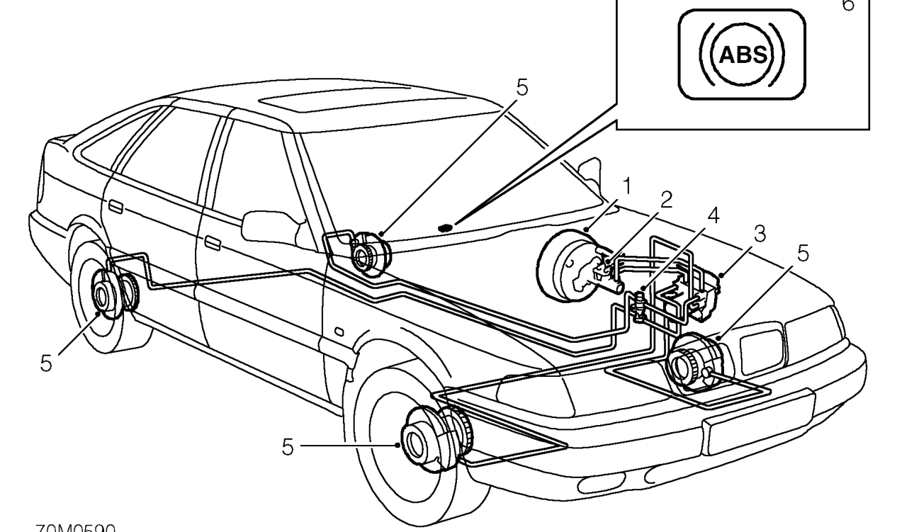
- Servo unit
- Master cylinder - twin valve
- ABS modulator and control ECU assembly
- Brake pressure proportioning valve
OPERATION
Servo
Inlet manifold vacuum is transmitted through a hose and non-return valve to the servo. Inside the servo, this vacuum is felt on both sides of the diaphragm. When the brake pedal is pressed, the servo push rod opens a valve and allows atmospheric pressure to be drawn through the filter into the pedal side of the diaphragm. The pressure differential, acting on the diaphragm, increases the pressure being applied at the brake pedal and transmits it to the master cylinder through a push rod.
- Reluctor ring and wheel sensor
- ABS warning lamp - illuminates when ABS system has been shut down due to a fault being detected
Master cylinder
When the foot brake is applied the primary plunger moves up the bore of the cylinder and the pressure created acts in conjunction with the primary spring to overcome the secondary spring, thus moving the secondary plunger up the bore of the cylinder simultaneously. Initial movement of both plungers causes them to be pushed off their stop pins, thus closing both primary and secondary centre valves. Further movement of the plungers pressurises the fluid which is directed into the two separate hydraulic circuits connected to the hydraulic modulator.
The primary circuit operates the RH front and LH rear brakes and the secondary circuit operates the LH front and RH rear brakes.
Parts & tools for this job For 1996 Rover 800
- PARTBrake padsSearch: Rover 800 1996 brake pads
- TOOLBrake bleeder kitSearch: one man brake bleeder kit
- FLUIDBrake fluidSearch: brake fluid
Links open Amazon search results in a new tab. As an Amazon Associate I earn from qualifying purchases.