
Main printed circuit
- Make
- Rover
- Model
- Coupé, Cabriolet & Tourer 200/400 Coupé, Cabriolet & Tourer Workshop Manual
- Section
- Repairs › Main printed circuit
InstrumentsMain printed circuit
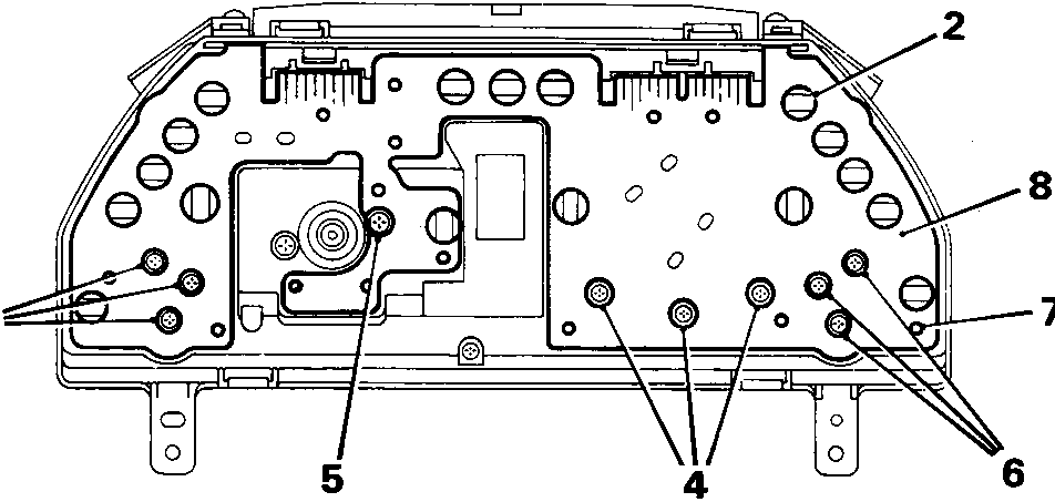
8RM 0777A
MAIN PRINTED CIRCUIT
Service Repair No. 88.20.23
Remove
- Remove instrument pack.
- Noting their fitted positions, turn anti-clockwise and remove all bulbs and bulb holders.
- Remove 3 screws securing fuel gauge.
- Remove 3 screws securing tachometer.
- Remove screw securing speedometer.
- Remove 3 screws securing temperature gauge.
- Release main printed circuit from locating pins.
- Remove main printed circuit.
Refit
- Fit main printed circuit.
- Secure main printed circuit to locating lugs.
- Fit and tighten 3 screws securing temperature gauge.
- Fit and tighten screw securing speedometer.
- Fit and tighten 3 screws securing tachometer.
- Fit and tighten 3 screws securing fuel gauge.
- Fit bulb and bulb holders, turn clockwise to secure.
- Fit instrument pack.
Parts & tools for this job For Rover Coupé, Cabriolet & Tourer
- TOOLDigital multimeterSearch: automotive digital multimeter
- PARTAssorted fuse kitSearch: car fuse assortment kit
- TOOLWire crimper and connector kitSearch: wire crimper connector kit
Links open Amazon search results in a new tab. As an Amazon Associate I earn from qualifying purchases.