
Remove
- Make
- Rover
- Model
- Coupé, Cabriolet & Tourer 200/400 Coupé, Cabriolet & Tourer Workshop Manual
- Section
- Repairs › Remove
InstrumentsRemove
Service Repair No. Selection indicator 88.20.28
Service Repair No. Anti - theft L.E.D. 86.55.97
Remove
- Remove instrument pack.
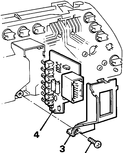
- Remove screw securing cover.
- Remove cover.
- Withdraw indicator panel from mounting slots.
Refit
- Fit indicator panel to mounting slots.
- Fit cover and tighten screw.
- Fit instrument pack.
OIL PRESSURE SWITCH 1.4 AND 1.6
Service Repair No. 12.60.50
Remove
- Disconnect battery earth lead.
- 1.4 with air conditioning only: Raise front of vehicle.
WARNING: Support on safety stands.
- 1.4 with air conditioning only: Remove underbelly panel, see BODY – Repairs.
- 1.4 with air conditioning only: Position drain tray below filter.
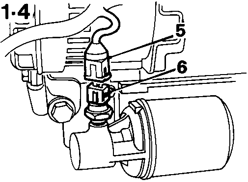
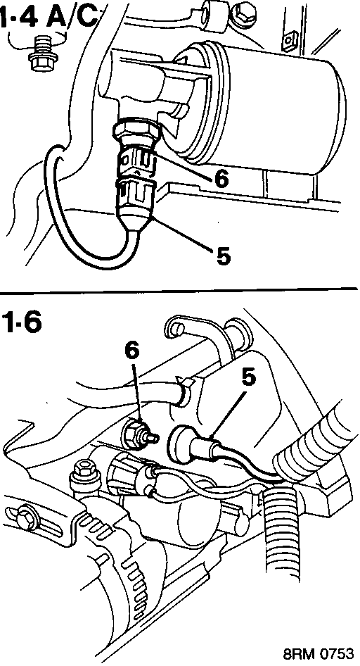
- Disconnect lead from oil pressure switch.
- Remove oil pressure switch.
Refit
- Clean oil pressure switch threads.
- Fit oil pressure switch and tighten to:
1.6 = 18 Nm
1.4 = 12 Nm - Connect lead to oil pressure switch.
- 1.4 with air conditioning only: Fit underbelly panel, see BODY – Repairs.
- 1.4 with air conditioning only: Remove stands and lower vehicle.
- 1.4 with air conditioning only: Top - up engine oil.
- Connect battery earth lead.
Parts & tools for this job For Rover Coupé, Cabriolet & Tourer
- TOOLTorque wrenchSearch: 3/8 inch torque wrench
- TOOLSocket setSearch: socket set metric
- BOOKHaynes manualSearch: Haynes manual Rover Coupé, Cabriolet & Tourer
Links open Amazon search results in a new tab. As an Amazon Associate I earn from qualifying purchases.