
Refit
- Make
- Rover
- Model
- Coupé, Cabriolet & Tourer 200/400 Coupé, Cabriolet & Tourer Workshop Manual
- Section
- Repairs › Refit
InstrumentsRefit
Service Repair No. 88.25.32
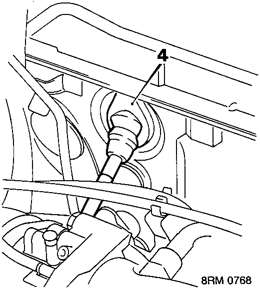
- Release cable grommet from bulkhead.
- Remove instrument pack.
- Fit tape to cable retainer at speedometer end to assist with cable removal.
- Withdraw cable through holes in steering column support bracket.
- Pull cable through bulkhead.
- Remove cable.
- Remove grommet from cable.
- Remove tape from end of cable.
Refit
- Fit tape to end of new cable.
- Fit grommet to cable.
- Position cable in vehicle.
- Feed cable through bulkhead.
- Fit grommet to bulkhead.
- Gently ease down demist duct and feed cable through the steering column support bracket.
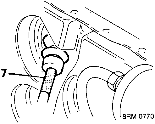
- Draw speedometer cable through grommet and ensure that coloured tape abuts grommet.
- Remove tape from end of cable.
- Fit instrument pack.
- Clean cable end and mating face.
- Fit cable to gearbox. Check retention.
- Fit cable securing clip.
- Secure cable rubber sleeve.
Remove
- Disconnect battery earth lead.
- Open taildoor.
- Release parcel tray cords from taildoor.
- Remove parcel tray.
- Open R.H. side rear door.
- Fold down rear seat.
- Raise carpet.
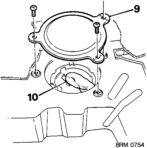
- Remove screws securing access plate to floor.
- Remove access plate.
- Release multiplug cover.
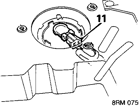
- Disconnect multiplug from tank unit.
Parts & tools for this job For Rover Coupé, Cabriolet & Tourer
- TOOLTorque wrenchSearch: 3/8 inch torque wrench
- TOOLSocket setSearch: socket set metric
- BOOKHaynes manualSearch: Haynes manual Rover Coupé, Cabriolet & Tourer
Links open Amazon search results in a new tab. As an Amazon Associate I earn from qualifying purchases.