
Manual steering rack – 1.6 (page 2 of 2)
- Make
- Rover
- Model
- Coupé, Cabriolet & Tourer 200/400 Coupé, Cabriolet & Tourer Workshop Manual
- Section
- Repairs
SteeringManual steering rack – 1.6 · page 2 of 2
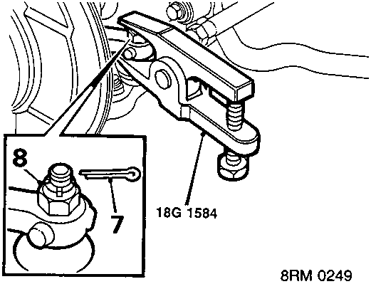
- Remove 2 split pins from track rod end ball joint nuts.
- Remove 2 ball joint nuts.
- Break taper joints using tool 18G 1584.
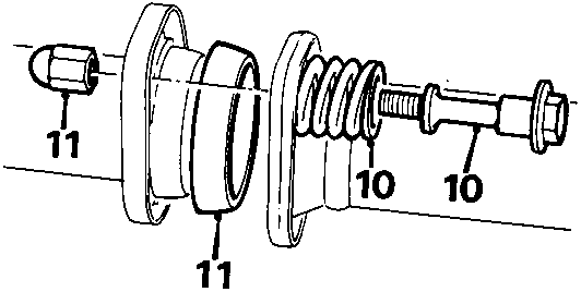
- Remove 2 bolts, exhaust front pipe to catalytic converter and remove 2 springs.
- Collect nuts and sealing ring from exhaust, discard nuts.
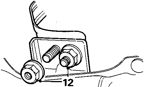
- Remove 2 nuts securing front exhaust pipe mounting bracket and lower exhaust.
Manual transmission only
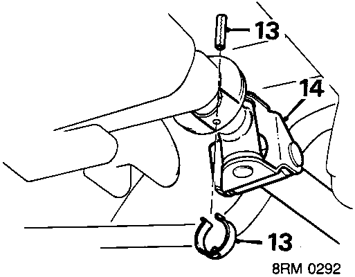
- Remove roll pin retaining clip, remove roll pin from gear change selector rod.
- Disconnect selector rod from transmission.
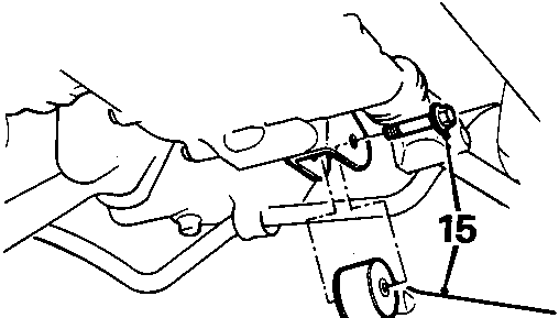
- Remove bolt securing steady rod and release steady rod from transmission.
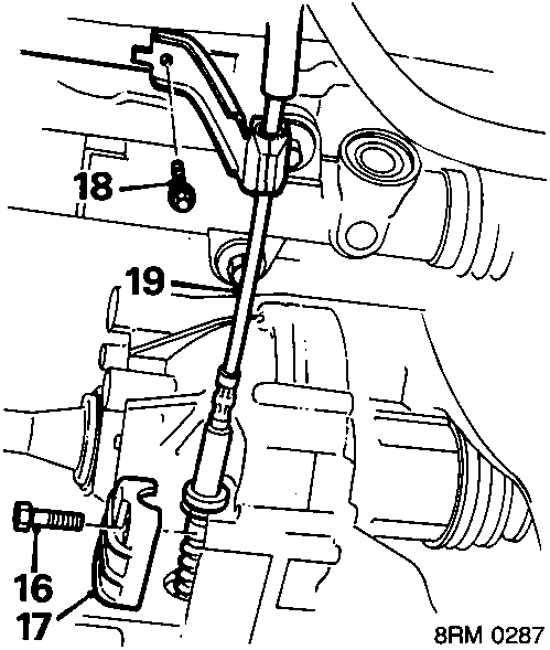
Automatic transmission only
- Remove bolt, gear selector cable clamp to gearbox.
- Remove cable clamp.
- Remove bolt gear selector cable bracket to crossmember.
- Release cable and pull fully rearwards.
Parts & tools for this job For Rover Coupé, Cabriolet & Tourer
- TOOLTie rod end toolSearch: tie rod end puller
- TOOLBall joint separatorSearch: ball joint separator
- FLUIDPower steering fluidSearch: Rover power steering fluid
Links open Amazon search results in a new tab. As an Amazon Associate I earn from qualifying purchases.