
Inlet manifold - r + r and replace seal
- Make
- Fiat
- Model
- 500 Factory Service Manual
- Year
- 2007–2024
- Section
- Inlet and exhaust manifolds › Inlet manifold - r + r and replace seal
INLET MANIFOLD - R + R AND REPLACE SEAL
Removing
- Position the vehicle on a lift.
Op. 5530B52 BATTERY SUPPORT/DRIP TRAY - R.R
Op. 1048A23 COLD AIR INTAKE FOR AIR FILTER - R.R
Op. 1048A10 AIR FILTER ASSEMBLY - R.R.
Op. 1008C34 BRACKET ON GEARBOX FOR LOWER REACTION ROD - R.R.
- Release the rear silencer and the central section of the exhaust pipe from the flexible mounts.
This operation is necessary to facilitate removing the intake manifold later, due to the reduced manifold working space in the engine compartment.
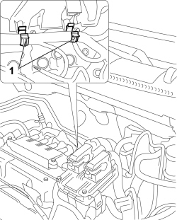
1. Release the engine wiring from the retaining clips secured to the intake manifold.
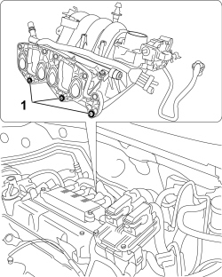
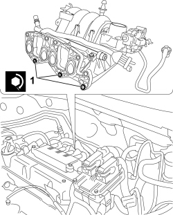
1. Undo the lower bolts securing the intake manifold to the cylinder head.
- Lower the lift.
1. Discharge the fuel pressure from the single fuel pipe, using the specific tool.
| Tool | Description | Function | Validity |
|---|---|---|---|
| 1.870.684.000 | Quick coupling connector | Pressure exhaust on single fuel manifold pipe | 1.2 8V 1.4 16V |
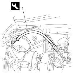
- Remove the tool at the end of the operation.
| Tool | Description | Function | Validity |
|---|---|---|---|
| 1.870.684.000 | Quick coupling connector | Pressure exhaust on single fuel manifold pipe | 1.2 8V 1.4 16V |
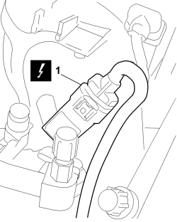
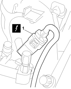
1. Disconnect the electrical connection for the aspirated air pressure/temperature sensor.
| Description | Connector | |
|---|---|---|
| 1 | Air pressure - temperature sensor | See K044 AIR TEMPERATURE/PRESSURE SENSOR |
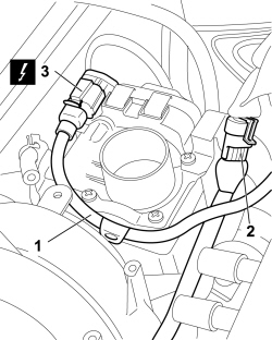
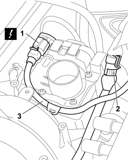
1. Release the electrical wiring for the built-in throttle body actuator from the retaining springs.
2. Release the electrical coupling of the injector wiring from the support bracket on the throttle body.
3. Disconnect the electrical connection for the integrated throttle body actuator.
| Description | Connector | |
|---|---|---|
| 3 | Throttle body actuator | See N075 BUILT-IN THROTTLE BODY ACTUATOR |
Position a suitable hydraulic lift to support the engine.
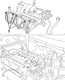
1. Undo the upper nuts securing the intake manifold to the cylinder head.
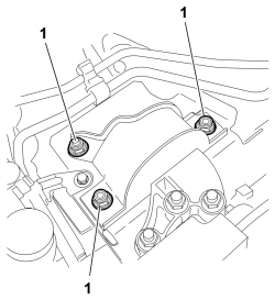
1. Undo the engine flexible mounting nuts on the body, engine side.
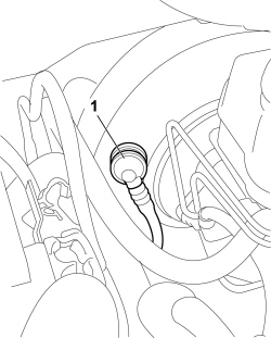
1. Disconnect the brake servo valve and free the pipe from the retaining clip.
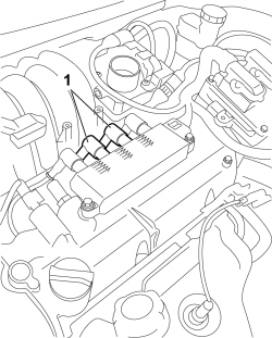
1. Remove the electrical cables for the second and third spark plugs, disconnecting both ends of the connection.
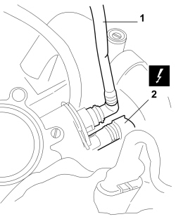
1. Disconnect the quick coupling for the fuel vapour recovery pipe.
2. Disconnect the electrical connection for the fuel vapour enablement solenoid.
| Description | Connector | |
|---|---|---|
| 2 | Fuel vapour recovery solenoid valve | See L010 FUEL VAPOUR RECOVERY SOLENOID VALVE |
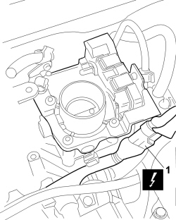
1. Disconnect the injector electrical wiring coupling.
| Description | Connector | |
|---|---|---|
| 1 | Injector coupling | See D081 INJECTOR JUNCTION |
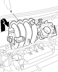
1. Lower the hydraulic lift until the intake manifold can be removed from its housing.
Turn the intake manifold in the appropriate direction to remove it from its housing.
Take care not to damage part of the bodywork whilst removing the intake manifold.
- Dismantle the intake manifold at the bench.
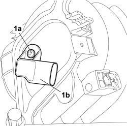
1. Undo retaining bolts (1a) and remove air pressure/temperature sensor (1b).
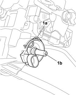
1. Open retaining band (1a) and remove fuel vapour enablement solenoid (1b) from the manifold housing.
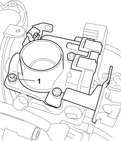
1. Undo the retaining bolts and remove the throttle body.
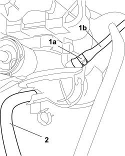
1. Open retaining band (1a) and disconnect brake servo pipe (1b).
2. Detach the vacuum pipe.
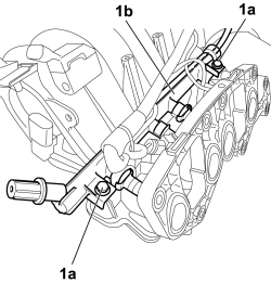
1. Undo bolts (1a) and remove common rail (1b) assembly.
Refitting
- Position the common rail assembly and tighten the bolts.
- Connect the brake servo pipe and secure it using the retainer band.
- Connect the vacuum pipe.
- Position the throttle body and tighten the retaining bolts.
- Position the fuel vapour enablement solenoid and secure it with the retaining clips.
- Position the air temperature/pressure sensor and tighten the retaining bolt.
- Fit the intake manifold in place.
1. Connect the injector electrical wiring coupling.
| Description | Connector | |
|---|---|---|
| 1 | Injector coupling | See D081 INJECTOR JUNCTION |
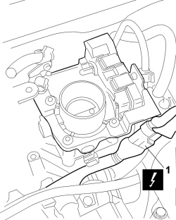
- Connect the electrical cables for the second and third spark plugs, spark plug and ignition coil side.
- Connect the brake servo valve and attach the pipe to the retaining clip.
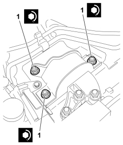
1. Tighten the engine flexible mounting nuts on the body, engine side, to the recommended torque.
| Component | Fastening | dia | Value (daNm) | Validity |
|---|---|---|---|---|
| Engine side flexible block (on body) | Nut | M10x1.25 | 5.0 | T.i.T |
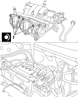
1. Tighten the upper nuts securing the intake manifold to the cylinder head to the recommended torque.
| Component | Fastening | dia | Value (daNm) | Validity |
|---|---|---|---|---|
| Intake manifold (on cylinder head) | Nut | M8x1.25 | 2.5 | 1.2 8V |
- Remove the hydraulic jack from underneath the engine.
1. Connect the electrical connection for the built-in throttle body actuator.
| Description | Connector | |
|---|---|---|
| 1 | Throttle body actuator | See N075 BUILT-IN THROTTLE BODY ACTUATOR |
2. Attach the electrical coupling for the injector wiring to the support bracket on the throttle body.
3. Attach the electrical wiring for the built-in throttle body actuator to the retaining clips.
1. Connect the electrical connection for the aspirated air pressure/temperature sensor.
| Description | Connector | |
|---|---|---|
| 1 | Air pressure - temperature sensor | See K044 AIR TEMPERATURE/PRESSURE SENSOR |
1. Tighten the lower bolts securing the intake manifold to the cylinder head to the recommended torque.
| Component | Fastening | dia | Value (daNm) | Validity |
|---|---|---|---|---|
| Intake manifold (on cylinder head) | Bolt | M8x1.25x45 | 2.5 | 1.2 8V |
| Component | Fastening | dia | Value (daNm) | Validity |
|---|---|---|---|---|
| Intake manifold (on cylinder head) | Bolt | M8x1.25x35 | 2.5 | 1.2 8V |
- Attach the engine wiring to the retaining clips secured to the intake manifold.
- Attach the rear silencer and the central section of the exhaust pipe to the flexible mounts.
Op. 1008C34 BRACKET ON GEARBOX FOR LOWER REACTION ROD - R.R.
Op. 1048A10 AIR FILTER ASSEMBLY - R.R.
Op. 1048A23 COLD AIR INTAKE FOR AIR FILTER - R.R
Op. 5530B52 BATTERY SUPPORT/DRIP TRAY - R.R
- Remove the vehicle from the lift.
Removing
- Position the vehicle on a lift.
- Disconnect the negative battery terminal.
| Description | Connector | |
|---|---|---|
| Battery | See A001 BATTERY |
Op. 1048A23 COLD AIR INTAKE FOR AIR FILTER - R.R
Op. 1048A10 AIR FILTER ASSEMBLY - R.R.
Op. 1048A32 HOSE FROM AIR FILTER TO INTAKE MANIFOLD - R + R
1. Discharge the fuel pressure from the single fuel pipe using the special tool.
| Tool | Description | Function | Validity |
|---|---|---|---|
| 1.870.684.000 | Quick coupling connector | Pressure exhaust on single fuel manifold pipe | 1.2 8V 1.4 16V |
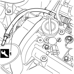
- Remove the tool at the end of the operation.
| Tool | Description | Function | Validity |
|---|---|---|---|
| 1.870.684.000 | Quick coupling connector | Pressure exhaust on single fuel manifold pipe | 1.2 8V 1.4 16V |
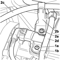
1. Undo the fixing bolt (1a) and place the intake air temperature/pressure sensor (1b) to one side.
2. Undo the fixing bolt (2a) and place the mounting bracket (2b) for the water return pipes from the thermostat unit to the expansion valve (2c) and the fuel supply pipes (2d) to one side.
1. Working the rapid connector, disconnect the fuel supply pipe to the single manifold pipe.
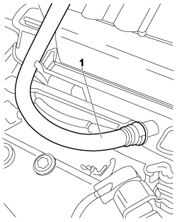
1. Adjust the rapid connector and disconnect the fuel vapour recovery pipe.
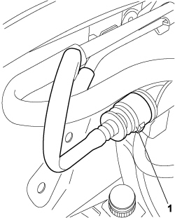
1. Open the retaining band (1a) and disconnect the brake servo pipe (1b), intake manifold side.
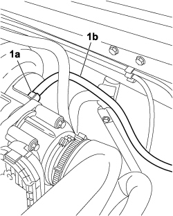
Op. 1056B15 THROTTLE BODY INTERGRAL WITH MDS - R.R.
1. Disconnect the oil vapour recovery pipe, intake manifold side.
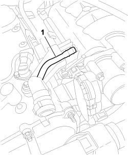
1. Detach the electrical connection for the fuel vapour recovery solenoid.
| Description | Connector | |
|---|---|---|
| 1 | Fuel vapour recovery solenoid valve | See L010 FUEL VAPOUR RECOVERY SOLENOID VALVE |
2. Disconnect the pipe on the fuel vapour recovery solenoid valve.
3. Disconnect the electrical coupling for the injectors and release the wiring from the mounting bracket.
| Description | Connector | |
|---|---|---|
| 3 | Injector coupling | See D081 INJECTOR JUNCTION |
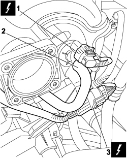
1. Working underneath the vehicle, open the retaining clips behind the intake manifold and release the engine cable loom.
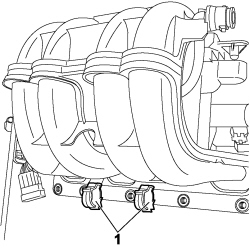
1. Undo the nuts (1a) and bolts (1b) securing the windscreen base support.
2. Undo the bolts fixing the windscreen base trim to the support.
The above operations are carried out on both sides of the windscreen base trim and support.
3. Release the bonnet housing seal along the perimeter in contact with the windscreen base trim.
These operations are necessary to assist the operation of extracting the intake manifold from its housing thereby avoiding the risk of damaging the components on account of the limited space for working in.
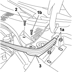
1. Undo the fixing bolts (1a) and remove the intake manifold assembly (1b) from the housing.
- Proceed with dismantling the intake manifold at the benche.
2. Undo the fixing bolts (2a) and remove the single fuel pipe assembly (2b).
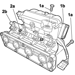
1. Undo the fixing bolts (1a) and remove the fuel vapour recovery enablement solenoid valve (1b) releasing the pipe from the retaining clip.
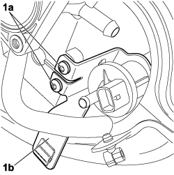
Refitting
- Place the fuel vapour recovery enablement solenoid valve in position and tighten the fixing bolts.
- Secure the fuel vapour recovery enablement solenoid valve pipe to the retaining clip.
1. Place the single fuel pipe (1a) in position on the intake manifold and tighten the fixing bolts (1b).
2. Fit the intake manifold (2a) in place and tighten the fixing bolts (2b) to the recommended torque.
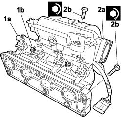
- Tighten the nuts and the bolts securing the windscreen base support.
- Tighten the bolts fixing the windscreen base trim to the support.
The above operations are carried out on both sides of the windscreen base trim and support.
- Fit the bonnet housing seal in position.
- Working underneath the vehicle, secure the engine cable loom to the retaining clips behind the intake manifold.
1. Connect the electrical connection for the fuel vapour recovery solenoid.
| Description | Connector | |
|---|---|---|
| 1 | Fuel vapour recovery solenoid valve | See L010 FUEL VAPOUR RECOVERY SOLENOID VALVE |
2. Connect the pipe on the fuel vapour recovery solenoid valve. Connect the electrical coupling for the injectors and release the wiring from the mounting bracket.
3. Connect the electrical coupling for the injectors and release the wiring from the mounting bracket.
| Description | Connector | |
|---|---|---|
| 3 | Injector coupling | See D081 INJECTOR JUNCTION |
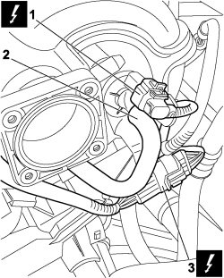
- Connect the oil vapour recovery pipe, intake manifold side.
Op. 1056B15 THROTTLE BODY INTERGRAL WITH MDS - R.R.
- Connect the brakeservo pipe to the intake manifold and fasten it using the retaining band.
- Connect the fuel vapour recovery pipe.
- Connect the fuel supply pipe to the single fuel pipe.
- Reposition the intake air temperature/pressure sensor and tighten the fixing bolt.
- Reposition the mounting bracket for the water return pipes from the thermostat unit to the expansion valve and the fuel supply pipes and tighten the fixing bolt.
Op. 1048A32 HOSE FROM AIR FILTER TO INTAKE MANIFOLD - R + R
Op. 1048A10 AIR FILTER ASSEMBLY - R.R.
Op. 1048A23 COLD AIR INTAKE FOR AIR FILTER - R.R
- Connect the negative battery terminal.
| Description | Connector | |
|---|---|---|
| Battery | See A001 BATTERY |
- Remove the vehicle from the lift.
Removing
Op. 5530B52 BATTERY SUPPORT/DRIP TRAY - R.R
Op. 1048A10 AIR FILTER ASSEMBLY - R.R.
Op. 1048A23 COLD AIR INTAKE FOR AIR FILTER - R.R
Op. 1048B44 RIGID AIR SUPPLY PIPE BETWEEN HEAT EXCHANGER AND INTAKE MANIFOLD - R.R.
Op. 1080D28 OIL VAPOUR RECOVERY PIPE BETWEEN SEPARATOR AND TURBO - R.R.
Op. 1080D34 ENGINE OIL VAPOUR SEPARATOR - R + R
Op. 1080C82 E.G.R. - VALVE HEAT EXCHANGER ASSEMBLY - CONNECTOR PIPES - R.R.
Op. 7210E22 R.R. WINDSCREEN BASE TRIM
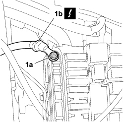
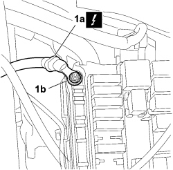
1. Undo nut (1a) and disconnect engine compartment junction unit power cable (1b).
| Description | Component | |
|---|---|---|
| 1b | ENGINE COMPARTMENT JUNCTION UNIT | See B001 JUNCTION UNIT |
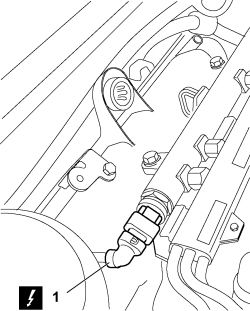
1. Detach the fuel pressure sensor electrical connection.
| Description | Component | |
|---|---|---|
| 1 | FUEL PRESSURE SENSOR | See K083 FUEL PRESSURE SENSOR |
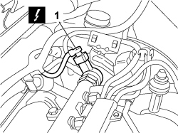
1. Disconnect the electrical connection for the fuel pressure regulator.
| Description | Component | |
|---|---|---|
| 1 | FUEL PRESSURE REGULATOR | See N077 FUEL PRESSURE REGULATOR |
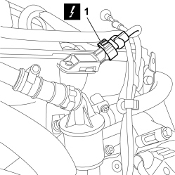
1. Disconnect the electrical connection for the turbocharging sensor.
| Description | Component | |
|---|---|---|
| 1 | TURBOCHARGING SENSOR | See K082 SUPERCHARGING SENSOR |
- Release the engine electrical wiring from the retaining bands housed on the intake manifold.
1. Undo retaining bolts (1a) and remove intake manifold (1b) from its housing.
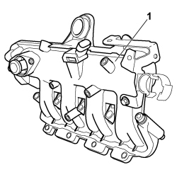
Refitting
1. Fit intake manifold (1a) in place and tighten retaining bolts (1b) to the recommended torque.
| Component | Fastening | dia | Value (daNm) | Validity |
|---|---|---|---|---|
| Intake manifold (on cylinder head) | Bolt | M8x1.25x65 | 2.5 | 1.3 Multijet |
| Component | Fastening | dia | Value (daNm) | Validity |
|---|---|---|---|---|
| Intake manifold (on cylinder head) | Bolt | M8x1.25x20 | 2.5 | 1.3 Multijet |
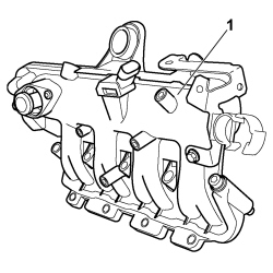
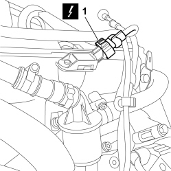
1. Connect the electrical connection for the turbocharging sensor.
| Description | Component | |
|---|---|---|
| 1 | TURBOCHARGING SENSOR | See K082 SUPERCHARGING SENSOR |
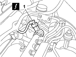
1. Connect the electrical connection for the fuel pressure regulator.
| Description | Component | |
|---|---|---|
| 1 | FUEL PRESSURE REGULATOR | See N077 FUEL PRESSURE REGULATOR |
1. Connect the electrical connection for the fuel pressure sensor.
| Description | Component | |
|---|---|---|
| 1 | FUEL PRESSURE SENSOR | See K083 FUEL PRESSURE SENSOR |
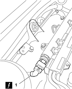
1. Connect power cable (1a) to the engine compartment junction unit and tighten nut (1b).
- Attach the engine electrical wiring to the retaining bands housed on the intake manifold.
Op. 7210E22 R.R. WINDSCREEN BASE TRIM
Op. 1080C82 E.G.R. - VALVE HEAT EXCHANGER ASSEMBLY - CONNECTOR PIPES - R.R.
Op. 1080D34 ENGINE OIL VAPOUR SEPARATOR - R + R
Op. 1080D28 OIL VAPOUR RECOVERY PIPE BETWEEN SEPARATOR AND TURBO - R.R.
Op. 1048B44 RIGID AIR SUPPLY PIPE BETWEEN HEAT EXCHANGER AND INTAKE MANIFOLD - R.R.
Op. 1048A23 COLD AIR INTAKE FOR AIR FILTER - R.R
Op. 1048A10 AIR FILTER ASSEMBLY - R.R.
Parts & tools for this job For 2007 Fiat 500
- PARTExhaust gasketSearch: Fiat 500 2007 exhaust gasket
- TOOLPenetrating oilSearch: penetrating oil
- TOOLOBD2 scannerSearch: OBD2 scanner
Links open Amazon search results in a new tab. As an Amazon Associate I earn from qualifying purchases.