
System cable loom - r.r.
- Make
- Fiat
- Model
- Croma Factory Service Manual
- Year
- 2005–2010
- Section
- Diesel injection system › System cable loom - r.r.
SYSTEM CABLE LOOM - R.R.
Removing
- Position the vehicle on a lift.
Op. 1016A10 SOUND-PROOFING COVER - R.R
Op. 5530B52 BATTERY SUPPORT/DRIP TRAY - R.R
Op. 1048A10 AIR FILTER ASSEMBLY - R.R.
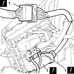
1. Open the junction unit cover and disconnect the electrical connections.
| Description | Connector | |
|---|---|---|
| 1 | Engine compartment junction unit | See B001 ENGINE COMPARTMENT JUNCTION UNIT |
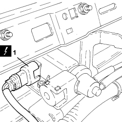
1. Disconnect the electrical connection from the turbocharger vane position actuator solenoid valve.
| Description | Connector | |
|---|---|---|
| 1 | Turbine variable geometry control solenoid | See L036 TURBINE VARIABLE GEOMETRY CONTROL SOLENOID VALVE |
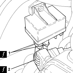
1. Disconnect the electrical connections from the heater plugs control unit.
| Description | Connector | |
|---|---|---|
| 1 | Heater plugs control unit | See M015 HEATER PLUGS CONTROL UNIT |
2. Disconnect the intermediate engine wiring coupling.
| Description | Connector | |
|---|---|---|
| 2 | Engine cables/engine services cable coupling | See D029 ENGINE CABLES/ENGINE SERVICES CABLE COUPLING |
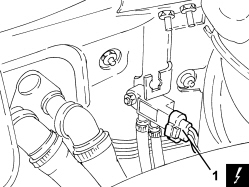
1. Disconnect the electrical connection from the particle filter differential pressure sensor.
| Description | Connector | |
|---|---|---|
| 1 | FAP differential pressure sensor | See K187 FAP DIFFERENTIAL PRESSURE SENSOR |
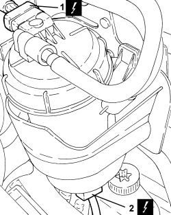
1. Disconnect the electrical connection from the fuel filter.
| Description | Connector | |
|---|---|---|
| 1 | Fuel temperature sensor and heating resistance | See K100 TEMPERATURE SENSOR AND HEATING RESISTANCE |
2. Disconnect the electrical connection from the water presence sensor on the fuel filter.
| Description | Connector | |
|---|---|---|
| 2 | Water in diesel filter sensor | See K031 WATER IN DIESEL FILTER SENSOR |
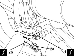
1. Disconnect the electrical connection from the air conditioning system multi-stage pressure switch.
| Description | Connector | |
|---|---|---|
| 1 | 4 stage pressure switch | See K010 4 STAGE PRESSURE SWITCH |
2. Undo the nut (2a) and disconnect the earth lead (2b).
Op. 7055B54 UNDER ENGINE PROTECTION/GUARD - R.R.
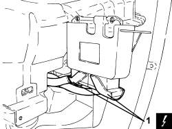
1. Disconnect the electrical connections from the diesel electronic injection system control unit.
| Description | Connector | |
|---|---|---|
| 1 | Engine management control unit | See M010 ENGINE MANAGEMENT CONTROL UNIT |
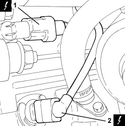
1. Disconnect the electrical connection from the engine rpm sensor.
| Description | Connector | |
|---|---|---|
| 1 | Engine rpm sensor | See K046 RPM SENSOR |
2. Disconnect the electrical connection from the engine oil level sensor.
| Description | Connector | |
|---|---|---|
| 2 | Engine oil level sensor | See K032 ENGINE OIL LEVEL SENSOR |
1. Disconnect the electrical connection from the engine oil pressure warning light switch.
| Description | Connector | |
|---|---|---|
| 1 | Insufficient engine oil pressure sensor (switch) | See K030 INSUFFICIENT ENGINE OIL PRESSURE SENSOR |
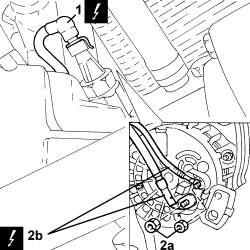
2. Undo the fixing nuts (2a) and disconnect the electrical connections (2b) from the alternator.
| Description | Connector | |
|---|---|---|
| 2b | Alternator | See A010 ALTERNATOR |
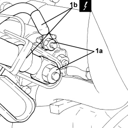
1. Undo the nuts (1a) and disconnect the electrical connections (1b) from the starter motor.
| Description | Connector | |
|---|---|---|
| 1b | Starter motor | See A020 STARTER MOTOR |
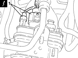
1. Disconnect the electrical connections from the power steering pump.
| Description | Connector | |
|---|---|---|
| 1 | Electric steering control unit | See M086 ELECTRIC STEERING CONTROL UNIT |
The version with ABS is shown in the diagram. The version with ESP comes with the two electrical connections indicated plus a third electrical connection with wiring for connection to the steering angle sensor.
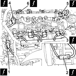
1. Disconnect the electrical connection from the cam angle sensor.
| Description | Connector | |
|---|---|---|
| 1 | Timing sensor | See K047 TIMING SENSOR |
2. Disconnect the electrical connection of the air conditioner compressor.
| Description | Connector | |
|---|---|---|
| 2 | Air conditioning compressor engagement electro-magnet | See L020 AIR CONDITIONING COMPRESSOR ENGAGEMENT ELECTRO-MAGNET |
3. Disconnect the electrical connections from the injectors.
| Description | Connector | |
|---|---|---|
| 3 | Injector | See N070 INJECTOR |
4. Disconnect the electrical connection from the fuel pressure regulator on the injector single manifold.
| Description | Connector | |
|---|---|---|
| 4 | Fuel pressure regulator on rail | See N087 FUEL PRESSURE REGULATOR ON RAIL |
5. Disconnect the electrical connection from the fuel pressure sensor.
| Description | Connector | |
|---|---|---|
| 5 | Fuel pressure sensor | See K083 FUEL PRESSURE SENSOR |
6. Disconnect the electrical connections from the heater plugs.
| Description | Connector | |
|---|---|---|
| 6 | Heater plugs | See A040 HEATER PLUGS |
1. Disconnect the electrical connection for the pressure relief sensor.
| Description | Connector | |
|---|---|---|
| 1 | Supercharging sensor | See K082 SUPERCHARGING SENSOR |
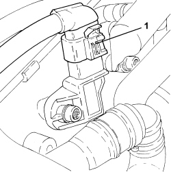
1. Disconnect the electrical connection from the fuel pressure regulator on the pressure pump.
| Description | Connector | |
|---|---|---|
| 1 | Fuel pressure regulator | See N077 FUEL PRESSURE REGULATOR |
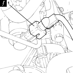
1. Disconnect the electrical connection from the EGR system solenoid valve
| Description | Connector | |
|---|---|---|
| 1 | EGR solenoid valve | See L030 EGR SOLENOID VALVE |
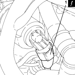
Op. 1080D34 ENGINE OIL VAPOUR SEPARATOR - R + R
1. Disconnect the electrical connection from the throttle control shaft valve for the intake manifolds.
| Description | Connector | |
|---|---|---|
| 1 | Flow modifier solenoid valve | See L064 FLOW MODIFYING SOLENOID VALVE |
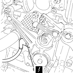
1. Disconnect the electrical connection from the engine coolant temperature sensor.
| Description | Connector | |
|---|---|---|
| 1 | Engine coolant temperature sensor/sender unit | See K036 ENGINE COOLANT TEMPERATURE SENSOR/SENDER UNIT |
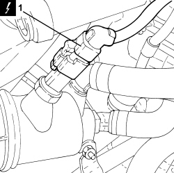
1. Disconnect the electrical connection from the throttle casing.
| Description | Connector | |
|---|---|---|
| 1 | Integrated throttle casing actuator | See N075 INTEGRATED THROTTLE CASING ACTUATOR |
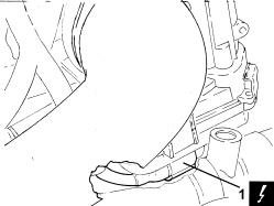
- Release the system cable loom from the fastenings and remove it.
Refitting
- Place the system cable loom in its housing and secure it.
- Connect the electrical connection to the throttle casing.
- Connect the electrical connection to the engine coolant temperature sensor.
- Connect the electrical connection to the throttle control shaft valve for the intake manifolds.
Op. 1080D34 ENGINE OIL VAPOUR SEPARATOR - R + R
- Connect the electrical connection to the EGR system solenoid valve
- Connect the electrical connection to the fuel pressure regulator on the pressure pump.
- Connect the electrical connection for the pressure relief sensor.
- Connect the electrical connections to the heater plugs.
- Connect the electrical connection to the fuel pressure sensor.
- Connect the electrical connection to the fuel pressure regulator on the injector single manifold.
- Connect the electrical connections to the injectors.
- Connect the electrical connection of the air conditioner compressor.
- Connect the electrical connection to the cam angle sensor.
- Connect the electrical connections to the power steering pump.
- Connect the electrical connections to the starter motor and secure them using the nuts.
- Connect the electrical connections to the alternator and secure them using the nuts.
- Connect the electrical connection to the engine oil pressure warning light switch.
- Connect the electrical connection to the engine oil level sensor.
- Connect the electrical connection for the engine rpm sensor.
- Connect the electrical connections to the diesel electronic injection system control unit.
Op. 7055B54 UNDER ENGINE PROTECTION/GUARD - R.R.
- Connect the earth lead and tighten the nut.
- Connect the electrical connection to the air conditioning system multi-stage pressure switch.
- Connect the electrical connection to the water presence sensor on the fuel filter.
- Connect the electrical connection to the fuel filter.
- Connect the electrical connection to the particle filter differential pressure sensor.
- Connect the intermediate engine wiring coupling.
- Connect the electrical connections to the heater plugs control unit.
- Connect the electrical connection to the turbocharger vane position actuator solenoid valve.
- Connect the electrical connections and close the junction unit cover.
Op. 1048A10 AIR FILTER ASSEMBLY - R.R.
Op. 5530B52 BATTERY SUPPORT/DRIP TRAY - R.R
Op. 1016A10 SOUND-PROOFING COVER - R.R
- Remove the vehicle from the lift.
Removing
- Position the vehicle on a lift.
Op. 1016A10 SOUND-PROOFING COVER - R.R
Op. 5530B52 BATTERY SUPPORT/DRIP TRAY - R.R
Op. 1048A10 AIR FILTER ASSEMBLY - R.R.
Op. 4450B04 RIGHT FRONT WHEEL - R.R
Op. 7055B66 ENGINE COMPARTMENT DUST COVER IN RIGHT FRONT WHEEL ARCH - R.R.
Op. 7055B91 RIGHT FRONT WHEEL ARCH LINER - R.R.
Op. 7055B54 UNDER ENGINE PROTECTION/GUARD - R.R.
1. Disconnect the electrical connections from the diesel electronic injection system control unit.
| Description | Connector | |
|---|---|---|
| 1 | Engine management control unit | See M010 ENGINE MANAGEMENT CONTROL UNIT |
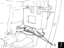
1. Disconnect the electrical connection of the air conditioner compressor.
| Description | Connector | |
|---|---|---|
| 1 | Air conditioning compressor engagement electro-magnet | See L020 AIR CONDITIONING COMPRESSOR ENGAGEMENT ELECTRO-MAGNET |
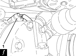
1. Disconnect the electrical connection from the air conditioning system multi-stage pressure switch.
| Description | Connector | |
|---|---|---|
| 1 | 4 stage pressure switch | See K010 4 STAGE PRESSURE SWITCH |
2. Undo the nut (2a) and disconnect the earth lead (2b).
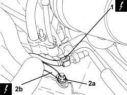
1. Release the electrical wiring from the securing bands and move it aside.
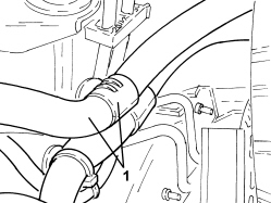
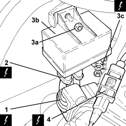
1. Disconnect the intermediate engine wiring coupling.
..
| Description | Connector | |
|---|---|---|
| 1 | Engine cables/engine services cable coupling | See D029 ENGINE CABLES/ENGINE SERVICES CABLE COUPLING |
2. Disconnect the electrical connections from the heater plugs control unit.
| Description | Connector | |
|---|---|---|
| 2 | Heater plugs control unit | See M015 HEATER PLUGS CONTROL UNIT |
3. Undo the nut (3a) and remove the heater plugs control unit (3b) after having disconnected the remaining electrical connection (3c).
| Description | Connector | |
|---|---|---|
| 3c | Heater plugs control unit | See M015 HEATER PLUGS CONTROL UNIT |
4. Disconnect the intermediate coupling for the cam angle sensor.
| Description | Connector | |
|---|---|---|
| 4 | Timing sensor | See K047 TIMING SENSOR |
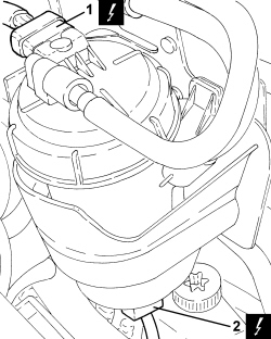
1. Disconnect the electrical connection from the fuel filter.
| Description | Connector | |
|---|---|---|
| 1 | Fuel temperature sensor and heating resistance | See K100 TEMPERATURE SENSOR AND HEATING RESISTANCE |
2. Disconnect the electrical connection from the water presence sensor on the fuel filter.
| Description | Connector | |
|---|---|---|
| 2 | Water in diesel filter sensor | See K031 WATER IN DIESEL FILTER SENSOR |
1. Disconnect the electrical connection from the EGR system solenoid valve
| Description | Connector | |
|---|---|---|
| 1 | EGR solenoid valve | See L030 EGR SOLENOID VALVE |
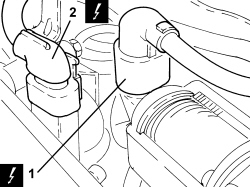
1. Disconnect the electrical connection from the engine coolant temperature sensor.
| Description | Connector | |
|---|---|---|
| 1 | Engine coolant temperature sensor/sender unit | See K036 ENGINE COOLANT TEMPERATURE SENSOR/SENDER UNIT |
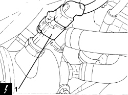
1. Disconnect the electrical connection from the throttle casing.
| Description | Connector | |
|---|---|---|
| 1 | Integrated throttle casing actuator | See N075 INTEGRATED THROTTLE CASING ACTUATOR |
2. Disconnect the electrical connection from the fuel pressure sensor.
| Description | Connector | |
|---|---|---|
| 2 | Fuel pressure sensor | See K083 FUEL PRESSURE SENSOR |
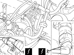
1. Disconnect the electrical connection for the exhaust gas temperature sensor on the particle filter.
| Description | Connector | |
|---|---|---|
| 1 | Downstream catalytic converter temperature sensor | See K188 |
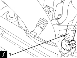
1. Disconnect the electrical connections from the injectors.
| Description | Connector | |
|---|---|---|
| 1 | Injector | See N070 INJECTOR |
2. Undo the bolts (2a) and rmove the electrical wiring (2b) aside.
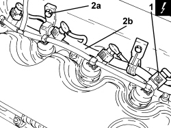
1. Undo the bolts (1a) and move the fuel return manifold (1b) sideways.
2. Disconnect the electrical connection from the fuel pressure regulator on the pressure pump.
| Description | Connector | |
|---|---|---|
| 2 | Fuel pressure regulator on pressure pump | See N077 FUEL PRESSURE REGULATOR |
3. Disconnect the electrical connection from the fuel pressure regulator on the injector single manifold.
| Description | Connector | |
|---|---|---|
| 2 | Fuel pressure regulator on rail | See N087 FUEL PRESSURE REGULATOR ON RAIL |
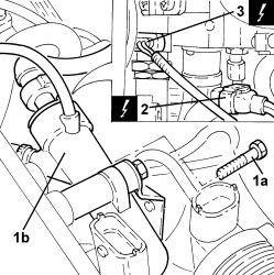
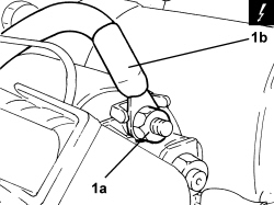
1. Undo the nut (1a) and disconnect the earth lead (1b) from the starter motor.
| Description | Connector | |
|---|---|---|
| 1b | Starter motor | See A020 STARTER MOTOR |
1. Disconnect the electrical connection from the engine oil pressure warning light switch.
| Description | Connector | |
|---|---|---|
| 1 | Insufficient engine oil pressure sensor (switch) | See K030 INSUFFICIENT ENGINE OIL PRESSURE SENSOR |
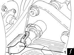
1. Disconnect the electrical connection from the engine rpm sensor.
| Description | Connector | |
|---|---|---|
| 1 | Engine rpm sensor | See K046 RPM SENSOR |
2. Disconnect the electrical connection from the engine oil level sensor.
| Description | Connector | |
|---|---|---|
| 2 | Engine oil level sensor | See K032 ENGINE OIL LEVEL SENSOR |
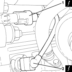
1. Undo the nut (1a) and disconnect the earth lead (1b) from the alternator.
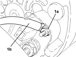
- Release the system cable loom from the fastenings and remove it.
Refitting
- Place the system cable loom in its housing and secure it.
- Connect the earth lead to the alternator and secure it using the nut.
- Connect the electrical connection to the engine oil level sensor.
- Connect the electrical connection for the engine rpm sensor.
- Connect the electrical connection to the engine oil pressure warning light switch.
- Connect the earth lead to the starter motor and secure it using the nut.
- Connect the electrical connection to the fuel pressure regulator on the injector single manifold.
- Connect the electrical connection to the fuel pressure regulator on the pressure pump.
- Place the fuel return manifold pipe in its housing and secure it using the bolts.
- Place the electrical wiring in position and fasten it using the bolts.
- Connect the electrical connections to the injectors.
- Connect the electrical connection to the exhaust gas temperature sensor to the particle filter.
- Connect the electrical connection to the fuel pressure sensor.
- Connect the electrical connection to the throttle casing.
- Connect the electrical connection to the engine coolant temperature sensor.
- Connect the electrical connection for the pressure relief sensor.
- Connect the electrical connection for the E.G.R. solenoid valve.
- Connect the electrical connection to the water presence sensor on the fuel filter.
- Connect the electrical connection to the fuel filter.
- Connect the intermediate coupling for the cam angle sensor.
- Connect the electrical connections to the heater plugs control unit then place it in its housing and secure it using the nut.
- Connect the electrical connections to the heater plugs control unit.
- Connect the intermediate engine wiring coupling.
- Place the electrical wiring in position and fasten it to the bands.
- Connect the earth lead and tighten the nut.
- Connect the electrical connection to the air conditioning system multi-stage pressure switch.
- Connect the air conditioning compressor electrical connection.
- Connect the electrical connections to the diesel electronic injection system control unit.
Op. 7055B54 UNDER ENGINE PROTECTION/GUARD - R.R.
Op. 7055B91 RIGHT FRONT WHEEL ARCH LINER - R.R.
Op. 7055B66 ENGINE COMPARTMENT DUST COVER IN RIGHT FRONT WHEEL ARCH - R.R.
Op. 4450B04 RIGHT FRONT WHEEL - R.R
Op. 1048A10 AIR FILTER ASSEMBLY - R.R.
Op. 5530B52 BATTERY SUPPORT/DRIP TRAY - R.R
Op. 1016A10 SOUND-PROOFING COVER - R.R
- Remove the vehicle from the lift.
Removing
- Position the vehicle on a lift.
Op. 1016A10 SOUND-PROOFING COVER - R.R
Op. 5530B52 BATTERY SUPPORT/DRIP TRAY - R.R
Op. 1048A10 AIR FILTER ASSEMBLY - R.R.
1. Open the junction unit cover and disconnect the electrical connections.
| Description | Connector | |
|---|---|---|
| 1 | Engine compartment junction unit | See B001 ENGINE COMPARTMENT JUNCTION UNIT |
1. Disconnect the electrical connection from the turbocharger vane position actuator solenoid valve.
| Description | Connector | |
|---|---|---|
| 1 | Turbine variable geometry control solenoid | See L036 TURBINE VARIABLE GEOMETRY CONTROL SOLENOID VALVE |
1. Disconnect the electrical connections from the heater plugs control unit.
| Description | Connector | |
|---|---|---|
| 1 | Heater plugs control unit | See M015 HEATER PLUGS CONTROL UNIT |
2. Disconnect the intermediate engine wiring coupling.
| Description | Connector | |
|---|---|---|
| 2 | Engine cables/engine services cable coupling | See D029 ENGINE CABLES/ENGINE SERVICES CABLE COUPLING |
1. Disconnect the electrical connection from the particle filter differential pressure sensor.
| Description | Connector | |
|---|---|---|
| 1 | FAP differential pressure sensor | See K187 FAP DIFFERENTIAL PRESSURE SENSOR |
1. Disconnect the electrical connection from the water presence sensor on the fuel filter.
| Description | Connector | |
|---|---|---|
| 1 | Water in diesel filter sensor | See K031 WATER IN DIESEL FILTER SENSOR |
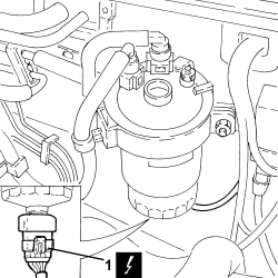
1. Disconnect the electrical connection from the air conditioning system multi-stage pressure switch.
| Description | Connector | |
|---|---|---|
| 1 | Linear sensor for fans | See K120 LINEAR SENSOR FOR FANS |
2. Undo the nut (2a) and disconnect the earth lead (2b).
Op. 7055B54 UNDER ENGINE PROTECTION/GUARD - R.R.
1. Disconnect the electrical connection from the diesel electronic injection system control unit.
| Description | Connector | |
|---|---|---|
| 1 | Engine management control unit | See M010 ENGINE MANAGEMENT CONTROL UNIT |
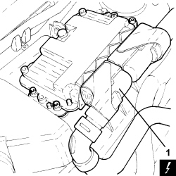
1. Disconnect the electrical connection from the engine rpm sensor.
| Description | Connector | |
|---|---|---|
| 1 | Engine rpm sensor | See K046 RPM SENSOR |
2. Disconnect the electrical connection from the engine oil level sensor.
| Description | Connector | |
|---|---|---|
| 2 | Engine oil level sensor | See K032 ENGINE OIL LEVEL SENSOR |
1. Disconnect the electrical connection from the engine oil pressure warning light switch.
| Description | Connector | |
|---|---|---|
| 1 | Insufficient engine oil pressure sensor (switch) | See K030 INSUFFICIENT ENGINE OIL PRESSURE SENSOR |
2. Undo the fixing nuts (2a) and disconnect the electrical connections (2b) from the alternator.
| Description | Connector | |
|---|---|---|
| 2b | Alternator | See A010 ALTERNATOR |
1. Undo the nuts (1a) and disconnect the electrical connections (1b) from the starter motor.
| Description | Connector | |
|---|---|---|
| 1b | Starter motor | See A020 STARTER MOTOR |
1. Disconnect the electrical connections from the power steering pump.
| Description | Connector | |
|---|---|---|
| 1 | Electric steering control unit | See M086 CONTROL UNIT |
The version with ABS is shown in the diagram. The version with ESP comes with the two electrical connections indicated plus a third electrical connection with wiring for connection to the steering angle sensor.
1. Disconnect the electrical connection from the cam angle sensor.
| Description | Connector | |
|---|---|---|
| 1 | Timing sensor | See K047 TIMING SENSOR |
2. Disconnect the electrical connection of the air conditioner compressor.
| Description | Connector | |
|---|---|---|
| 2 | Air conditioning compressor engagement electro-magnet | See L020 AIR CONDITIONING COMPRESSOR ENGAGEMENT ELECTRO-MAGNET |
3. Disconnect the electrical connections from the injectors.
| Description | Connector | |
|---|---|---|
| 3 | Injector | See N070 INJECTOR |
4. Disconnect the electrical connection from the fuel pressure regulator on the injector single manifold.
| Description | Connector | |
|---|---|---|
| 4 | Fuel pressure regulator on rail | See N087 FUEL PRESSURE REGULATOR ON RAIL |
5. Disconnect the electrical connection from the fuel pressure sensor.
| Description | Connector | |
|---|---|---|
| 5 | Fuel pressure sensor | See K083 FUEL PRESSURE SENSOR |
6. Disconnect the electrical connections from the heater plugs.
| Description | Connector | |
|---|---|---|
| 6 | Heater plugs | See A040 HEATER PLUGS |
1. Disconnect the electrical connection for the pressure relief sensor.
| Description | Connector | |
|---|---|---|
| 1 | Air pressure - temperature sensor | See K044 AIR PRESSURE - TEMPERATURE SENSOR |
1. Disconnect the electrical connection from the fuel pressure regulator on the pressure pump.
| Description | Connector | |
|---|---|---|
| 1 | Fuel pressure regulator | See N077 FUEL PRESSURE REGULATOR |
1. Disconnect the electrical connection from the EGR system solenoid valve
| Description | Connector | |
|---|---|---|
| 1 | EGR solenoid valve | See L030 EGR SOLENOID VALVE |
Op. 1080D34 ENGINE OIL VAPOUR SEPARATOR - R + R
1. Disconnect the electrical connection from the throttle control shaft valve for the inlet ducts.
| Description | Connector | |
|---|---|---|
| 1 | Flow modifier solenoid valve | See L064 FLOW MODIFYING SOLENOID VALVE |
1. Disconnect the electrical connection from the engine coolant temperature sensor.
| Description | Connector | |
|---|---|---|
| 1 | Engine coolant temperature sensor/sender unit | See K036 ENGINE COOLANT TEMPERATURE SENSOR/SENDER UNIT |
1. Disconnect the electrical connection from the throttle casing.
| Description | Connector | |
|---|---|---|
| 1 | Integrated throttle casing actuator | See N075 INTEGRATED THROTTLE CASING ACTUATOR |
- Release the system cable loom from the fastenings and remove it.
Refitting
- Place the system cable loom in its housing and secure it.
- Connect the electrical connection to the throttle casing.
- Connect the electrical connection to the engine coolant temperature sensor.
- Connect the electrical connection to the throttle control shaft valve for the inlet ducts.
Op. 1080D34 ENGINE OIL VAPOUR SEPARATOR - R + R
- Connect the electrical connection to the EGR system solenoid valve
- Connect the electrical connection to the fuel pressure regulator on the pressure pump.
- Connect the electrical connection for the pressure relief sensor.
- Connect the electrical connections to the heater plugs.
- Connect the electrical connection to the fuel pressure sensor.
- Connect the electrical connection to the fuel pressure regulator on the injector single manifold.
- Connect the electrical connections to the injectors.
- Connect the air conditioning compressor electrical connection.
- Connect the electrical connection to the cam angle sensor.
- Connect the electrical connections to the power steering pump.
- Connect the electrical connections to the starter motor and secure them using the nuts.
- Connect the electrical connections to the alternator and secure them using the nuts.
- Connect the electrical connection to the engine oil pressure warning light switch.
- Connect the electrical connection to the engine oil level sensor.
- Connect the electrical connection for the engine rpm sensor.
- Connect the electrical connection to the diesel electronic injection system control unit.
Op. 7055B54 UNDER ENGINE PROTECTION/GUARD - R.R.
- Connect the earth lead and tighten the nut.
- Connect the electrical connection to the air conditioning system multi-stage pressure switch.
- Connect the electrical connection to the water presence sensor on the fuel filter.
- Connect the electrical connection to the particle filter differential pressure sensor.
- Connect the intermediate engine wiring coupling.
- Connect the electrical connections to the heater plugs control unit.
- Connect the electrical connection to the turbocharger vane position actuator solenoid valve.
- Connect the electrical connections and close the junction unit cover.
Op. 1048A10 AIR FILTER ASSEMBLY - R.R.
Op. 5530B52 BATTERY SUPPORT/DRIP TRAY - R.R
Op. 1016A10 SOUND-PROOFING COVER - R.R
- Remove the vehicle from the lift.
Parts & tools for this job For 2005 Fiat Croma
- PARTGlow plugsSearch: Fiat Croma 2005 glow plugs
- TOOLGlow plug socketSearch: glow plug socket
- TOOLDiesel compression testerSearch: diesel compression tester
Links open Amazon search results in a new tab. As an Amazon Associate I earn from qualifying purchases.