
Ds electric injection control unit - r r
- Make
- Fiat
- Model
- Stilo Factory Service Manual
- Year
- 2001–2007
- Section
- Diesel fuel injection › Ds electric injection control unit - r r
Ds electric injection control unit - r r
Removing
- 5530B56 BATTERY DRIP TRAY COVER - R.R.
Disconnect the battery negative terminal.
1. Disconnect the electrical connection from the injection electronic control unit.
| Name | Connector | |
|---|---|---|
| 1 | Engine management ECU | M10 |
2. Undo nut (2a) and release earth lead (2b).
| Name | Connector | |
|---|---|---|
| 2b | Injection ECU earth | C60 |
3. Undo the retaining bolts.
4. Remove the engine management control unit from its housing.
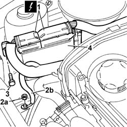
Removing
Disconnect the battery negative terminal.
- 1016A10 sound-proofing cover - r + r
1. Undo the retaining bolts.
2. Disconnect the electrical connections for the engine management control unit.
3. Remove engine control unit.
| Name | Connector | |
|---|---|---|
| 2 | Engine management ECU | M10A |
| Name | Connector | |
|---|---|---|
| 2 | Engine management ECU | M10B |
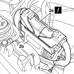
Refitting
Fit the control unit in its seat.
Tighten the bolts retaining the support bracket to the bodyshell.
Connect the electrical connections to the control unit.
| Name | Connector | |
|---|---|---|
| Engine management ECU | M10 |
Secure the earth lead to the body.
| Name | Connector | |
|---|---|---|
| Injection ECU earth | C60 |
Connect the battery negative terminal.
If the engine management control unit is replaced, the new control unit must be initialised after installation.
Carry out the manual control unit initialisation procedure.
Turn the ignition key to ON position
Wait 60 seconds, the time required for the control unit to save the learnt values in EPROM.
Turn the ignition key to the OFF position
Wait 10 seconds, the time required for the control unit to save the values obtained from connected electrical devices in the EPROM.
After carrying out the initialisation procedure, the power supply may be disconnected from the engine control unit (battery disconnection) without losing data.
New injectors and injection control unit have been introduced to improve engine operation and guarantee emission limits are respected in the long term. When replacing the injectors, note the following: the Bosch part number and injector category is engraved on the upper part of the magnet on each injector (1,2,3 inside a ring). This is determined on the basis of fuel quantity injected into the emission control point.
The graded injectors described above are complemented by a new injection control unit that is personalized according to the injector category
The modification will be implemented from October 2001 from engine no. 2805542.
If replacing a premodification engine injector control unit marked with the code C5603 supplied until stocks are exhausted, fit without carrying out any recognition operations on the injectors. Once old control unit stocks are used up, new units will be supplied. These should be recustomised using the active Injector classification procedure and treating the injectors of each cylinder as CATEGORY 2.
When replacing a postmodification control unit described by parts as D5603, this must be personalised using an Examiner tester. Carry out active injector classification diagnosis and store the injector categories for each cylinder again.
- 5530B56 BATTERY DRIP TRAY COVER - R.R.
Refitting
Fit the engine control unit into its seat on the battery cradle.
Connect the electrical connections for the engine management control unit.
| Name | Connector | |
|---|---|---|
| Engine management ECU | M10A |
| Name | Connector | |
|---|---|---|
| Engine management ECU | M10B |
Tighten the bolts to torque.
- 1016A10 sound-proofing cover - r + r
Connect the battery negative terminal.
Parts & tools for this job For 2001 Fiat Stilo
- PARTGlow plugsSearch: Fiat Stilo 2001 glow plugs
- TOOLGlow plug socketSearch: glow plug socket
- TOOLDiesel compression testerSearch: diesel compression tester
Links open Amazon search results in a new tab. As an Amazon Associate I earn from qualifying purchases.