
Fuel injectors
- Make
- Fiat
- Model
- Stilo Factory Service Manual
- Year
- 2001–2007
- Section
- Diesel fuel injection › Fuel injectors
Fuel injectors
Removing
- 1016A10 sound-proofing cover - r + r
- 1060F36 lines to injectors - r r
Disconnect the pipe from the injectors to the fuel recovery manifold from the manifold and injectors.
Disconnect the injector electrical connections
| Name | Connector | |
|---|---|---|
| Injector | N70 |
1. Undo the injector anchoring brackets securing nuts.
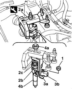
2. Fit injector removal device (2a). Ensure lifting bracket (2b) is fitted beneath the polygonal area of the injector.
3. Fit the second lifting bracket (3a) of the device under injector securing bracket (3b).
4. Tighten device nut (4a) and remove the injector (4b).
Repeat the operation for the remaining injectors.
| Name | Country | |
|---|---|---|
| 2a | Extractor | 1.870.739.000 |
Removing
- 1016A10 sound-proofing cover - r + r.
Disconnect the battery negative terminal.
| Name | Connector | |
|---|---|---|
| Battery | A1B |
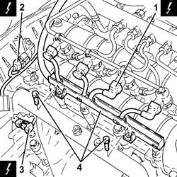
1. Disconnect the electrical connections from the injectors.
| Name | Connector | |
|---|---|---|
| 1 | Injector | N70 |
2. Disconnect the electrical connection from the cam angle sensor.
| Name | Connector | |
|---|---|---|
| 2 | Timing sensor | K47 |
3. Disconnect the electrical connection for the air conditioning compressor electromagnet coupling.
| Name | Connector | |
|---|---|---|
| 3 | Air conditioning compressor "on" electromagnet | L20 |
Undo the earth lead on the air conditioner compressor.
Release the electrical wiring from the band on the timing cover.
4. Undo the bolts fastening the cable duct and move the electrical wiring aside.
Refitting
Check the injectors are in good condition.
The injectors have been graded to improve engine operation and guarantee emission limits are respected in the long term. When replacing the injectors, note the following:
- The Bosch part number and injector category is engraved on the upper part of the magnet on each injector (1,2,3 inside a ring). This is determined on the basis of fuel quantity injected into the emission control point.
- The graded injectors described above are complemented by a new injection control unit that is personalized according to the injector category
The modification will be implemented from October 2001 from engine no. 2805542.
If a premodification engine injector is replaced, fit parts marked with the code C5603 and do not work on the injection control unit.
When replacing post-modification injectors, order parts identified as D5303 and no. 73501139. These parts are category 2C and require a specific injection control unit customisation procedure. This procedure is carried out using an Examiner diagostic tester and using the controls in the active Injector Classification function.
Fit the injectors complete with bracket.
Tighten the fixing nuts to torque.
| Fastening | Component | Ø | Value (daNm) | |
|---|---|---|---|---|
| Nut | INJECTORS(DIESEL) | M8 x 1.25 | 3 |
Fit the injection wiring and tighten the fixing bolts.
Connect the electrical connections to the injectors.
| Name | Connector | |
|---|---|---|
| Injector | N70 |
Connect the pipe clips to the injectors and connect the pipe to the return manifold.
- 1060F36 lines to injectors - r r
- 1016A10 sound-proofing cover - r + r
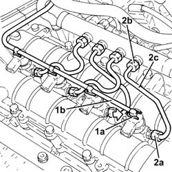
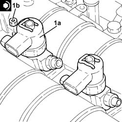
1. Push clips (1a) by hand and disconnect the pipe from the injectors to the fuel recovery manifold (1b), injectors side and move it aside.
2. Undo the connectors (2a), (2b) and remove the pipe from the fuel manifold to the injectors (2c).
Use new pipes from from fuel manifold to injectors upon reassembly.
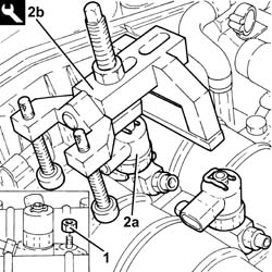
1. Undo the nuts fixing the injector brackets.
Remove the injectors (2a) complete with bracket using the tool (2b).
If the same injectors are being reused, mark the cylinder to which they belong so that they can be correctly refitted.
2.
If new fuel injectors are fitted:
determine the identification code stamped on the top;
check that the new injectors(s) is (are) recognized by the engine management control unit using the Examiner.
Start removal beginning with the fuel injector of cylinder no. 1 and continuing with the injectors for cylinders 2, 3 and 4.
| Name | Country | |
|---|---|---|
| 2b | Extractor | 1.870.897.300 |
Refitting
1. Refit the injectors (1a) complete with brackets and secure by tightening the nuts (1b) to the specified torque.
Start the refitting beginning with the injector for cylinder no. 4 and continuing with the injectors for cylinders 3, 2 and 1.
| Fastening | Component | Ø | Value (daNm) | |
|---|---|---|---|---|
| 1b | Nut | INJECTORS(DIESEL) | M8 x 1.25 | 2.5 |
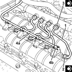
1. Fit new pipes from the fuel manifold to the injectors and fix them using the connectors without tightening them.
2. Tighten the connectors for the pipes from the fuel manifold to the injectors, injector side, to the recommended torque using a suitable spanner.
| Fastening | Component | Ø | Value (daNm) | |
|---|---|---|---|---|
| 2 | Connector | FUEL MANIFOLD LINE TO INJECTORS | M12 x 1.5 | (Injector side) 2.3 |
3. Tighten the connectors for the pipes between the fuel manifold and the injectors, fuel manifold side to the recommended torque using a suitable spanner.
| Fastening | Component | Ø | Value (daNm) | |
|---|---|---|---|---|
| 3 | Connector | FUEL MANIFOLD LINE TO INJECTORS | M12 x 1.5 | (Manifold side) 2.3 |
Clean the threaded seats for the above-mentioned pipe on the manifold and the injectors using heptane.
Connect the pipe from the injectors to the fuel recovery manifold to the injectors pushing it until the clips can be heard clicking into place.
Place the electrical wiring back in its housing and tighten the cable duct fixing bolts.
Connect the electrical connections to the injectors.
| Name | Connector | |
|---|---|---|
| Injector | N70 |
Connect the timing sensor electrical connection.
| Name | Connector | |
|---|---|---|
| Timing sensor | K47 |
Connect the electrical connection to the air conditioning compressor electromagnet coupling.
| Name | Connector | |
|---|---|---|
| Air conditioning compressor "on" electromagnet | L20 |
Tighten the earth lead nut to the air conditioner compressor.
Connect the negative (-) battery terminal
Parts & tools for this job For 2001 Fiat Stilo
- PARTFuel filterSearch: Fiat Stilo 2001 fuel filter
- TOOLFuel pressure test kitSearch: fuel pressure test kit
- TOOLFuel line disconnect toolSearch: fuel line disconnect tool
Links open Amazon search results in a new tab. As an Amazon Associate I earn from qualifying purchases.