
Up to 97.5MY illustrated (page 2 of 2)
- Make
- Rover
- Model
- 400 Workshop Manual
- Year
- 1995–2000
- Section
- Repairs
Engine - D SeriesUp to 97.5MY illustrated · page 2 of 2
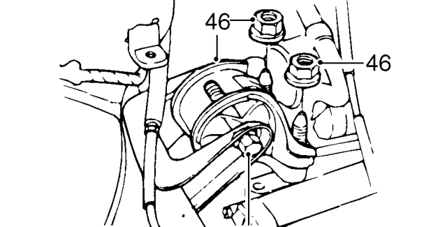
- Remove 2 nuts and through bolt bolt securing RH centre mounting to engine and body. Remove mounting.
- Raise engine approximately 150 mm. Check that all components are disconnected and lift clear of engine compartment.
CAUTION: Ensure lifting chains do not contact camshaft cover.
Refit
- Attach lifting chains to engine and gearbox, lower engine and gearbox into position ensuring rear mounting bracket is in position.
- Fit LH centre mounting, tighten nuts and bolt to 52 Nm.
- Fit through bolt, do not tighten.
- Fit RH centre mounting, tighten nuts to 64 Nm. Fit through bolt, do not tighten.
- Tighten RH and LH engine mounting through bolts to 74 Nm.
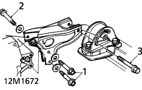
- Fit NEW bolts to rear mounting and tighten in sequence shown.
- Tighten bolts bracket to engine to 83 Nm. Tighten bolt bracket to mounting to 58 Nm.
- Position RH front mounting.
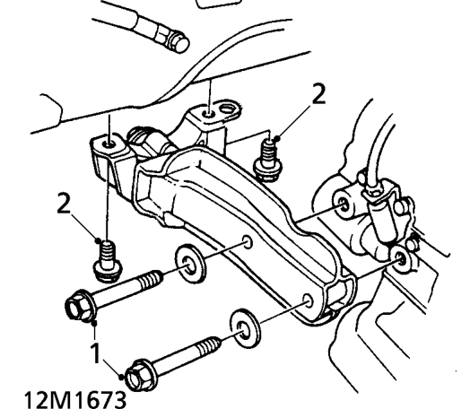
- Fit NEW bolts mounting to gearbox and tighten in sequence shown. Bracket to gearbox to 64 Nm and bracket to body to 44 Nm.
- Position LH front mounting and tighten bolts bracket to engine to 54 Nm. Tighten bolts bracket to body to 44 Nm.
- Disconnect lifting chains.
- Remove lifting bracket from engine.
- Clean drive shaft ends and differential oil seals.
- Fit new circlips to drive shafts.
- Lubricate oil seal running surface.
- Engage shafts in differential.
CAUTION: Pull joints to ensure clips are fully engaged and retain shafts.
- Engage lower ball joints in hubs. Tighten nuts to 49 Nm and fit new split pins.
- Fit steering ball joints to hubs. Tighten nuts to 39 Nm, align to next hole and fit new split pins.
- Fit selector cable to gearbox, fit NEW lock washer and tighten bolt to 14 Nm. Secure lock washer.
- Fit selector cable cover. Tighten bolts to 22 Nm.
- Fit anti-beaming bracket and exhaust support bracket. Tighten bolts securing anti-beaming bracket to engine to 24 Nm and bolts anti-beaming bracket to gearbox to 44 Nm.
- Fit exhaust front pipe. See MANIFOLD & EXHAUST SYSTEMS, Repairs.
- Connect oil cooler hoses. Secure with clips.
- Connect vacuum hoses to inlet manifold.
- Connect brake servo vacuum hose.
- Connect coolant top hose and heater hoses.
- Connect fuel return hose.
- Position power steering pump, fit securing bolts.
- Fit and tension power steering pump drive belt. See STEERING, Adjustments.
Parts & tools for this job For 1995 Rover 400
- PARTEngine gasket setSearch: Rover 400 1995 engine gasket set
- TOOLTorque wrenchSearch: 3/8 inch torque wrench
- TOOLFeeler gauge setSearch: feeler gauge set
Links open Amazon search results in a new tab. As an Amazon Associate I earn from qualifying purchases.