
Balancer shafts (page 2 of 2)
- Make
- Rover
- Model
- 600 Rover 600 Repair Manual - Volumes 1 and 2 - 2nd Edition
- Section
- Cylinder block: repairs
EngineBalancer shafts · page 2 of 2
- Inspect the surface of the balancer shaft journal and balancer bearing.
- Replace if there is wear, damage or discoloration on the surface of the bearing or the balancer shaft journal. When replacing the rear No. 1 bearing be sure to replace the oil pump housing with a new one.
Note: A mirror – like surface is normal.
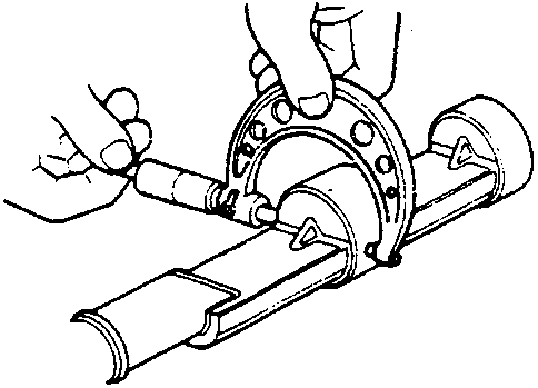
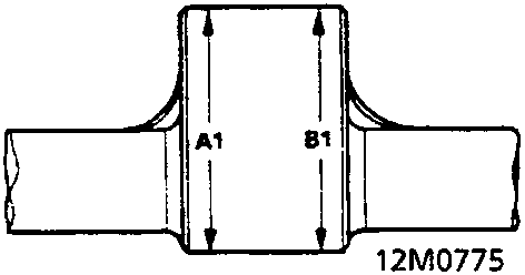
- Measure the taper at the edges of each journal.
Journal Taper (difference between A1 and B1)
Standard (New): 0.005 mm
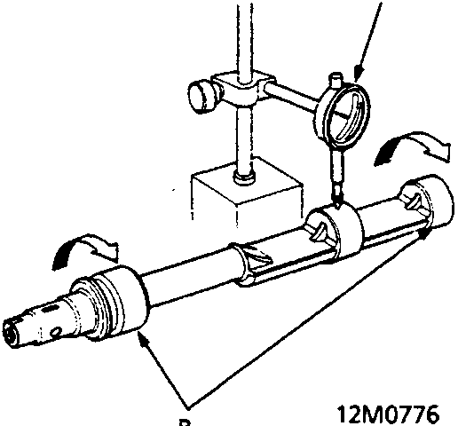
A Dial Indicator
B Support
- Support the balancer shaft with a lathe – type tool or V – blocks and measure the runout on the No. 2 journal of each balancer shaft to make sure the balancer shafts are not bent. When making the measurement rotate the balancer shaft two complete revolutions in the direction shown.
Balancer Shaft Total Indicated Runout
Standard (New): 0.02 mm
Service Limit: 0.03 mm
Parts & tools for this job For Rover 600
- PARTEngine gasket setSearch: Rover 600 engine gasket set
- TOOLTorque wrenchSearch: 3/8 inch torque wrench
- TOOLFeeler gauge setSearch: feeler gauge set
Links open Amazon search results in a new tab. As an Amazon Associate I earn from qualifying purchases.