
Right Side Cover (page 2 of 2)
- Make
- Rover
- Model
- 600 Rover 600 Repair Manual - Volumes 1 and 2 - 2nd Edition
- Section
- Cylinder block: repairs
EngineRight Side Cover · page 2 of 2
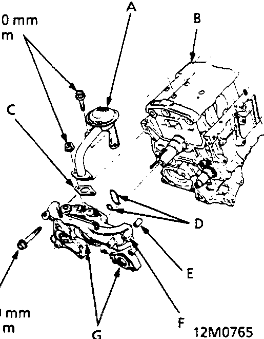
- Apply liquid gasket to the oil pump mating surface of the block (along the broken line shown) and to the threads of the bolts, then install the oil pump on the cylinder block using new O – rings, coated with clean engine oil.
- Apply grease to the lips of the oil seals. Then, install the oil pump while aligning the inner rotor with the crankshaft. When the pump is in place, clean any excess grease off the crankshaft and the balancer shaft, then check that the oil seal lips are not distorted.
- Install the baffle plate, then install the oil screen with new gasket.
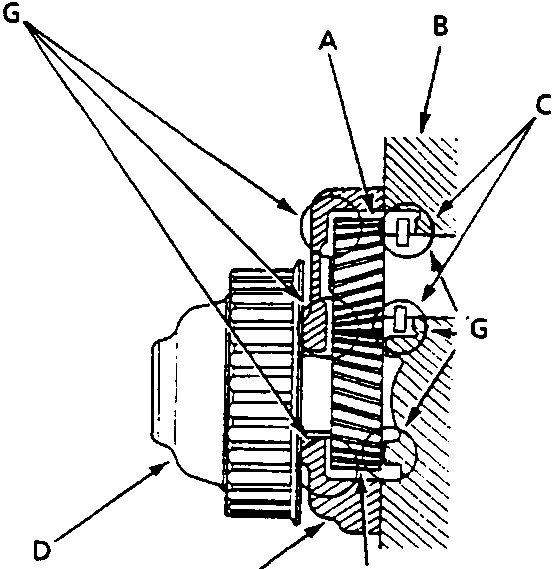
- Apply the molybdenum disulfide to the thrust surfaces of the balancer gears as shown, before installing the balancer driven gear and the balancer gear case.
Parts & tools for this job For Rover 600
- PARTEngine gasket setSearch: Rover 600 engine gasket set
- TOOLTorque wrenchSearch: 3/8 inch torque wrench
- TOOLFeeler gauge setSearch: feeler gauge set
Links open Amazon search results in a new tab. As an Amazon Associate I earn from qualifying purchases.