
D/valve train (page 4 of 6)
- Make
- Rover
- Model
- 600 Rover 600 Repair Manual - Volumes 1 and 2 - 2nd Edition
- Section
- Cylinder head/valve train: repairs
EngineD/valve train · page 4 of 6
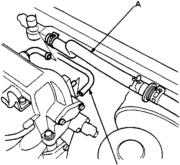
- Remove the brake booster vacuum hose and engine mount control vacuum tube (A/T only) from the intake manifold.
6 x 1.0 mm
12 Nm
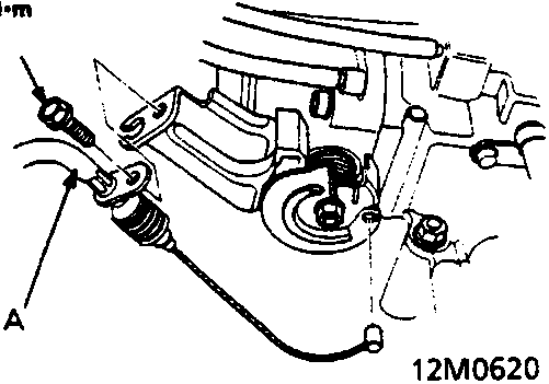
- Adjust the throttle cable when installing, see ENGINE MANAGEMENT SYSTEM – PGM – Fi.
- Remove the spark plug caps and the distributor.
- Remove the connector and the terminal from the alternator, then remove the engine wire harness from the cylinder head cover.
- Remove the following engine wire harness connectors from the cylinder head and the intake manifold:
- Four injector connectors
- Intake air temperature (IAT) sensor connector
- Idle air control (IAC) valve connector
- Throttle position (TP) sensor connector
- Exhaust gas recirculation (EGR) valve lift sensor connector
- Earth cable terminals
- Engine coolant temperature (ECT) sensor connector
- Heated oxygen sensor (HO2S) connector
- Engine coolant temperature switch A connector
- Engine coolant temperature gauge sending unit connector
- Ignition coil connector
- CKP/TDC/CYP sensor connector
- Vehicle speed sensor connector
- Remove the throttle cable, see ENGINE MANAGEMENT SYSTEM – PGM – Fi.
- Remove the throttle control cable (A/T only) from the throttle body.
Note:
- Take care not to bend the throttle cable when removing it. Always replace any kinked cable with a new one.
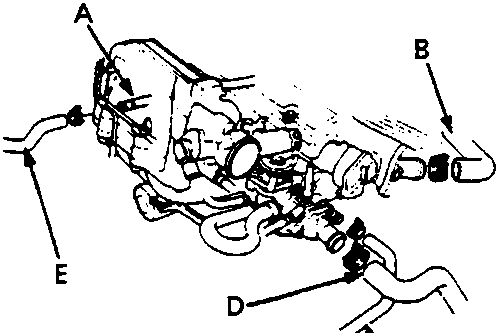
- Remove the upper and lower radiator hoses and heater hoses
Parts & tools for this job For Rover 600
- PARTEngine gasket setSearch: Rover 600 engine gasket set
- TOOLTorque wrenchSearch: 3/8 inch torque wrench
- TOOLFeeler gauge setSearch: feeler gauge set
Links open Amazon search results in a new tab. As an Amazon Associate I earn from qualifying purchases.