
D/valve train (page 5 of 6)
- Make
- Rover
- Model
- 600 Rover 600 Repair Manual - Volumes 1 and 2 - 2nd Edition
- Section
- Cylinder head/valve train: repairs
EngineD/valve train · page 5 of 6
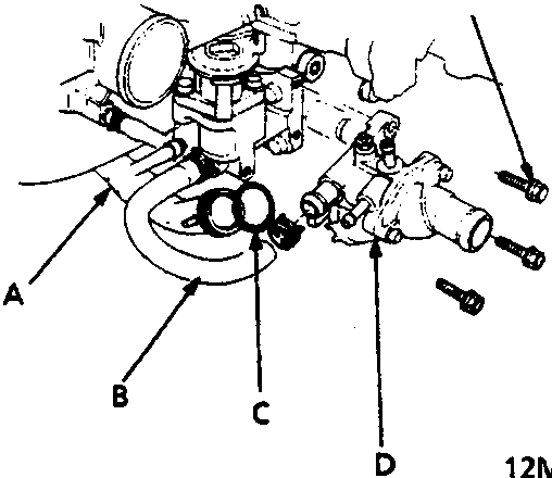
A Connecting pipe
B Bypass hose
C O – ring
D Thermostat assembly
- Remove the emission vacuum hoses and coolant bypass hoses from the intake manifold assembly.
- Remove the coolant bypass hose from the thermostat housing.
- Remove the thermostat assembly from the intake manifold.
- Replace the O – ring
- Remove the engine earth from the cylinder head cover.
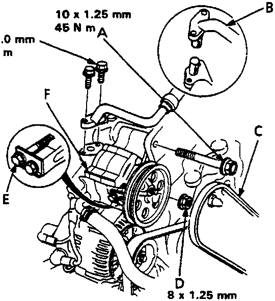
A Mounting bolt
B P/S pipe
C P/S pump belt
D Mounting nut
E Adjusting bolt
F P/S pump
- Remove the power steering (P/S) pipe, mounting bolt and nut. Loosen the adjusting bolt, then remove the pump belt and pump.
Note:
- Plug the pipe and the pump port.
- After installing, adjust the tension of the pump belt, see STEERING.
Parts & tools for this job For Rover 600
- PARTEngine gasket setSearch: Rover 600 engine gasket set
- TOOLTorque wrenchSearch: 3/8 inch torque wrench
- TOOLFeeler gauge setSearch: feeler gauge set
Links open Amazon search results in a new tab. As an Amazon Associate I earn from qualifying purchases.