
Abs5 ECU
- Make
- Rover
- Model
- 800 Workshop Manual
- Year
- 1996–1999
- Section
- Repairs › Abs5 ECU
BrakesAbs5 ECU
ABS5 ECU
Service repair no - 70.25.34
Remove
- Disconnect battery earth lead.
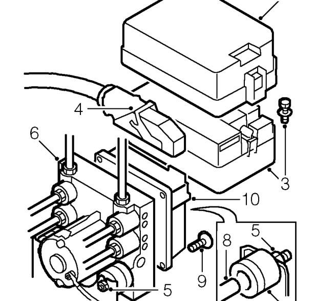
- Remove fusebox cover.
- Remove 2 screws and position fusebox aside
- Lift clip and disconnect multiplug from ABS ECU.
- Loosen 3 nuts securing ABS modulator and ECU assembly to mounting bracket.
- Release ABS modulator and ECU from bracket.
- Remove rubber mounting from spigot on ECU.
- Remove mounting spigot from ECU using a TX30 adapter.
- Remove 4 TX25 screws securing ECU to modulator.
- Remove ECU from modulator.
CAUTION: Take great care to prevent the entry of foreign matter into the rear of the modulator.
Refit
- Engage 2 multiplugs and fit ECU to modulator.
- Fit mounting spigot to ECU, DO NOT tighten.
- Fit screws securing ECU to modulator and tighten to 8 Nm.
- Tighten spigot to 15 Nm.
- Fit mounting rubber to spigot.
- Locate ECU and modulator assembly in mounting bracket and tighten nuts to 10 Nm.
- Connect multiplug to ECU and secure clip.
- Connect battery earth lead.
- Fit fusebox assembly.
- Check system using TestBook.
Parts & tools for this job For 1996 Rover 800
- PARTBrake padsSearch: Rover 800 1996 brake pads
- TOOLBrake bleeder kitSearch: one man brake bleeder kit
- FLUIDBrake fluidSearch: brake fluid
Links open Amazon search results in a new tab. As an Amazon Associate I earn from qualifying purchases.