
Remove (page 2 of 2)
- Make
- Rover
- Model
- Coupé, Cabriolet & Tourer 200/400 Coupé, Cabriolet & Tourer Workshop Manual
- Section
- Repairs
InstrumentsRemove · page 2 of 2
Refit
- Position instrument pack to fascia.
- Connect 3 multiplugs.
- Connect speedometer cable.
- Position instrument pack in fascia.
- 1.4 only: Connect upper and lower speedometer cables.
- 1.4 only: Tighten speedometer cable union to 9 Nm.

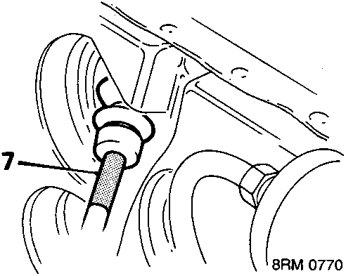
- Draw speedometer cable through grommet and ensure that coloured tape abuts the grommet.
- Fit 4 screws and tighten to secure instrument pack.
- Fit instrument cowl.
- Fit 4 screws and tighten to secure instrument cowl.
- Connect multiplugs to sun roof switch and switch pack.
- Fit sun roof switch and switch pack to cowl.
- Release column height adjuster.
- Raise column.
- Tighten column height adjuster.
- Connect battery earth lead.
Parts & tools for this job For Rover Coupé, Cabriolet & Tourer
- TOOLTorque wrenchSearch: 3/8 inch torque wrench
- TOOLSocket setSearch: socket set metric
- BOOKHaynes manualSearch: Haynes manual Rover Coupé, Cabriolet & Tourer
Links open Amazon search results in a new tab. As an Amazon Associate I earn from qualifying purchases.