
Remove (page 2 of 2)
- Make
- Rover
- Model
- Coupé, Cabriolet & Tourer 200/400 Coupé, Cabriolet & Tourer Workshop Manual
- Section
- Repairs
InstrumentsRemove · page 2 of 2
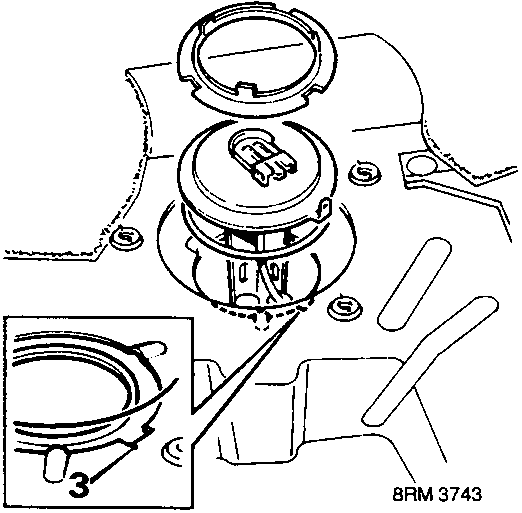
- Insert fuel tank unit float, align cover tag with cut out in fuel tank, and press cover into place.
CAUTION: To ensure accurate operation of the fuel gauge, ensure the float and calibration bar are clear of tank bottom when aligning tag to cut out.
- Fit locking ring, turn clockwise to engage.
- Secure locking ring by turning clockwise, using tool 18G 1595.
- Remove tool.
- Connect multiplug to tank unit, fit cover.
- Position access plate, fit and tighten screws.
Note: Ensure that locations pins mate correctly with plate.
- Reposition carpet.
- Close luggage compartment.
- Connect battery earth lead.

Parts & tools for this job For Rover Coupé, Cabriolet & Tourer
- TOOLTorque wrenchSearch: 3/8 inch torque wrench
- TOOLSocket setSearch: socket set metric
- BOOKHaynes manualSearch: Haynes manual Rover Coupé, Cabriolet & Tourer
Links open Amazon search results in a new tab. As an Amazon Associate I earn from qualifying purchases.