
Diesel injection wiring harness - r r
- Make
- Alfa Romeo
- Model
- 147 Factory Service Manual
- Year
- 2000–2004
- Section
- Diesel fuel injection › Diesel injection wiring harness - r r
Diesel injection wiring harness - r r
Removing
Position the vehicle on the ramp.
Proceed with removal - 7025A12 Engine front sound insulation COVER - R.R..
Proceed with removal - 7025A14 Bonnet LID - R.R..
Proceed with removal - 1016A10 sound-proofing cover - r + r.
Ensure that the ignition key is in the OFF position, then disconnect the negative battery terminal (-).
| Name | Connector | |
|---|---|---|
| Battery | A1B |
Proceed with removal - 7055B54 under-engine guard - r r.
Proceed with removal - 1076B70 exhaust pipe between pre-catalytic converter and catalytic converter - r r.
1. Disconnect the electrical connection from the engine oil pressure warning light switch.
| Name | Connector | |
|---|---|---|
| 1 | Engine oil pressure sensor | K30 |
2. Disconnect the electrical connection for the engine oil level sensor.
| Name | Connector | |
|---|---|---|
| 2 | Engine oil level sensor | K32 |
3. Disconnect the electrical connection for the rpm sensor.
| Name | Connector | |
|---|---|---|
| 3 | RPM sensor | K46 |
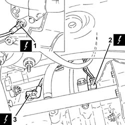
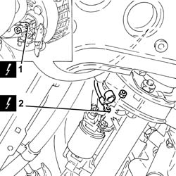
1. Disconnect the earth lead from the alternator
| Name | Connector | |
|---|---|---|
| 1 | Alternator | A10 |
2. Disconnect the earth lead from the starter motor.
| Name | Connector | |
|---|---|---|
| 2 | Starter motor | A20 |
1. Disconnect the electrical connection from the solenoid on the vacuum tank.
| Name | Connector | |
|---|---|---|
| 1 | Butterfly casing solenoid valve | L62 |
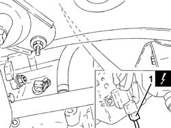
1. Disconnect the electrical connection from the turbocharger vane actuator solenoid.
| Name | Connector | |
|---|---|---|
| 1 | Variable geometry control solenoid | L15 |
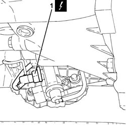
1. Disconnect the electrical connection from the air flow meter.
| Name | Connector | |
|---|---|---|
| 1 | Air flow meter | K41 |
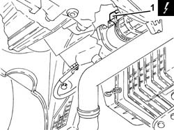
1. Disconnect the electrical connection from the engine coolant temperature sensor and release the wiring from the bands.
| Name | Connector | |
|---|---|---|
| 1 | Engine temperature sender unit | K36 |
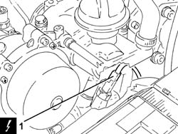
1. Disconnect the electrical connections from the injectors.
| Name | Connector | |
|---|---|---|
| 1 | Injector | N70 |
2. Disconnect the electrical connection from the cam angle sensor.
| Name | Connector | |
|---|---|---|
| 2 | Timing sensor. | K47 |
3. Disconnect the electrical connection for the air conditioning compressor.
| Name | Connector | |
|---|---|---|
| 3 | Air conditioning compressor engagement electro-magnet | L20 |
Release the electrical wiring from the band on the timing cover.
4. Undo the bolts fastening the cable duct and move the electrical wiring aside.
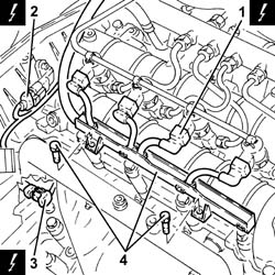
1. Disconnect the electrical connections from the heater plugs.
| Name | Connector | |
|---|---|---|
| 1 | Heater plug | A40 |
2. Disconnect the electrical connection from the fuel pressure sensor.
| Name | Connector | |
|---|---|---|
| 2 | Fuel pressure sensor | K83 |
3. Disconnect the electrical connection from the excess pressure sensor.
| Name | Connector | |
|---|---|---|
| 3 | Turbocharging sensor | K82 |
4. Disconnect the electrical connection from the E.G.R. valve.
| Name | Connector | |
|---|---|---|
| 4 | EGR solenoid | L30 |
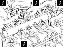
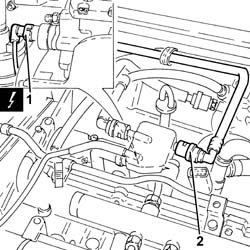
1. Disconnect the electrical connection from the fuel pressure regulator.
| Name | Connector | |
|---|---|---|
| 1 | Fuel pressure regulator | N77 |
2. Disconnect the rapid attachment for the fuel return pipe to the tank, fuel return manifold pipe side.
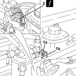
1. Undo the nuts (1a) and lift up the heater plugs control unit (1b) as much as necessary.
2. Disconnect the electrical connection from the pre-heating control unit.
| Name | Connector | |
|---|---|---|
| 2 | Plug preheating control unit | M15 |
Proceed with removal - 1008C10 power unit upper reaction link r r.
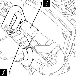
1. Connect the electrical connections to the diesel electronic injection control unit.
| Name | Connector | |
|---|---|---|
| 1 | Engine management ECU | M10A |
2. Disconnect the front engine coupling.
| Name | Connector | |
|---|---|---|
| 2 | Front / engine coupling | D4 |
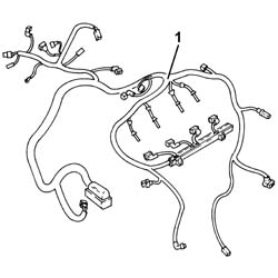
1. Release the spark plug cable loom from the securing bands and remove it.
Refitting
Place the cable loom back in its housing and fix it using the bands.
Connect the front enginec oupling.
Connect the electrical connection to the diesel electronic injection control unit.
Connect the rapid attachment for the fuel return pipe to the tank, fuel return manifold pipe side.
Proceed with refitting - 1008C10 power unit upper reaction link r r.
Connect the electrical connection to the pre-heating control unit.
Place the heater plugs control unit back in its housing and secure it using the nuts.
Connect the electrical connection to the fuel pressure regulator.
Connect the electrical connection to the E.G.R. system solenoid valve.
Connect the electrical connection to the excess pressure sensor.
Connect the electrical connection to the fuel pressure sensor.
Connect the electrical connections to the heater plugs.
Tighten the cable duct fixing bolts.
Fasten the electrical wiring to the band on the timing cover.
Connect the electrical connection to the air conditioner compressor
Connect the electrical connection to the cam angle sensor
Connect the electrical connections to the injectors.
Connect the electrical connection to the engine coolant temperature sensor and fasten the wiring to the bands.
Connect the electrical connection to the air flow meter.
Connect the electrical connection to the turbocharger vane actuator solenoid.
Connect the electrical connection to the solenoid on the vacuum tank.
Connect the earth lead to the starter motor.
Connect the earth lead to the alternator.
Connect the electrical connection for the rpm sensor.
Connect the electrical connection for the engine oil level sensor.
Connect the electrical connection to the engine oil pressure warning light switch.
Proceed with refitting - 1076B70 exhaust pipe between pre-catalytic converter and catalytic converter - r r.
Proceed with refitting - 7055B54 under-engine guard - r r.
Connect the negative (-) battery terminal.
Proceed with refitting - 1016A10 sound-proofing cover - r + r.
Proceed with refitting - 7025A14 Bonnet LID - R.R..
Proceed with refitting - 7025A12 Engine front sound insulation COVER - R.R..
Remove the car from the ramps.
Parts & tools for this job For 2000 Alfa Romeo 147
- PARTGlow plugsSearch: Alfa Romeo 147 2000 glow plugs
- TOOLGlow plug socketSearch: glow plug socket
- TOOLDiesel compression testerSearch: diesel compression tester
Links open Amazon search results in a new tab. As an Amazon Associate I earn from qualifying purchases.