
Introduction - timing system
- Make
- Fiat
- Model
- 500 Factory Service Manual
- Year
- 2007–2024
- Section
- Timing system › Introduction - timing system
INTRODUCTION - TIMING SYSTEM
A cast iron overhead camshaft operated by a timing belt.
There are the same number of suitably positioned, profiled cams on the shaft as there are valves to be operated; at the front there is provision for fitting a toothed pulley through which to receive movement from the crankshaft by means of a suitably tensioned timing belt (see chapter "repair procedures").
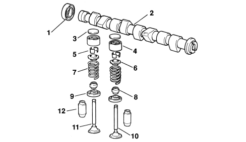
1. Camshaft oil seal
2. Camshaft
3. Tappet adjustment shim
4. Tappet
5. Half-cones
6. Upper shim
7. Spring
8. Oil seal
9. Lower shim
10. Inlet valve
11. Exhaust valve
12. Valve guide
The camshaft is the component which ensures the opening of the valves, via the cams, for the time required for the phases.
Since, in 4 stroke engines, the operating cycle takes place during two revolutions of the crankshaft, whilst the valves only have to open once, during the cycle the camshaft only completes one revolution; therefore the toothed pulley on the camshaft has double the number of teeth as the pulley on the crankshaft.
SPECIFICATIONS
Two ductile cast iron, overhead camshafts in a camshaft housing; they are operated by a belt and gears.
COMPOSITION
The shafts incorporate appropriately positioned and profiled cams; one for each valve to be operated.
The front of the exhaust shaft is designed for installation of a toothed pulley, which transmits drive from the crankshaft via an appropriately tensioned toothed belt. (see "Procedures for repairs")
A pair of gears, fitted behind the shafts, allows the transfer of drive from the exhaust shaft to the inlet shaft.
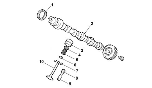
1. Camshaft oil seal
2. Camshaft
3. Tappet
4. Upper shim
5. Spring
6. Lower shim
7. Half-cones
8. Oil seal
9. Valve guide
10. Valve
HYDRAULIC TAPPETS
The hydraulic tappets used on this engine type automatically take up valve clearance during engine service. This offers the advantage of reducing:
- maintenance operations
- engine noise.
Operation in open stage
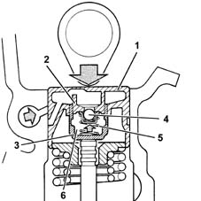
When the camshaft cam acts on cup (1) and thus piston (2), the oil trapped in chamber (6) due to the closure of ball valve (4) transmits the movement of piston (2) directly to hose (3) and consequently to the valve. At this stage, due to the high pressure acting on the oil, some of the oil in chamber (6) leaks through the tiny gap between piston (2) and hose (3).
Operation in closed stage
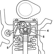
During valve closure, as long as the tappet pressed by the action of spring (5) follows the cam outline, a vacuum builds up inside chamber (6), bringing about opening of ball valve (4) to allow oil to enter. The oil taken into chamber (6) replaces the oil that leaked out during valve opening.
Timing drive belt route
The following figure shows the route of the timing drive belt.
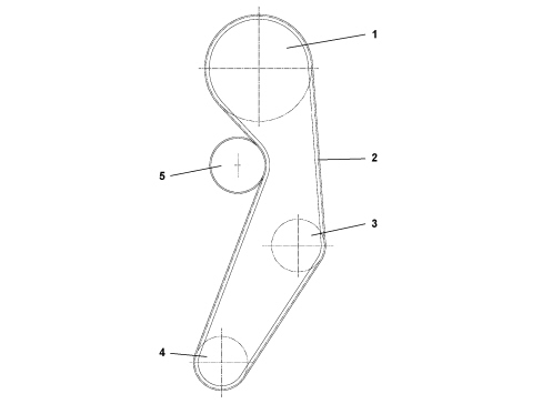
1. Camshaft duct gear
2. Timing belt
3. Water pump drive gear
4. Drive gear
5. Belt tensioner
Parts & tools for this job For 2007 Fiat 500
- PARTEngine gasket setSearch: Fiat 500 2007 engine gasket set
- TOOLTorque wrenchSearch: 3/8 inch torque wrench
- TOOLFeeler gauge setSearch: feeler gauge set
Links open Amazon search results in a new tab. As an Amazon Associate I earn from qualifying purchases.