
Operation
- Make
- Fiat
- Model
- Seicento Factory Service Manual
- Year
- 1998–2010
- Section
- Description and operation: Special accessories › Operation
An ECU manages the system checking all the components and triggering the airbag modules when necessary (the pretensioners have mechanical triggering).
Operation
Inside the ECU the following is installed:
- an accelerometric sensor, the signal from which, after processing by a microprocessor, can detect the entity of a crash and consequently trigger the airbags.
- A second safety sensor, mechanical, for checking, enables the triggering of the airbags.
The ECU only detects front crashes. It does not enable anything in the case of side crashes, nose-to-tail collisions or overturning of the vehicle.
LOCATION
The ECU is located under the vehicle and is rigidly fastened to the body: in this way the deceleration sensors inside it detect accurately the decelerations of the entire vehicle.
The ECU must always be installed with the stamped arrow pointing in the direction of the car travel.
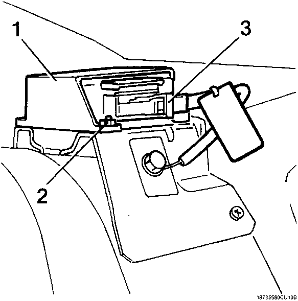
| Ref. | Name |
|---|---|
| 1 | ECU |
| 2 | ATTACHMENTS |
| 3 | ELECTRICAL CONNECTION |
ECU characteristics
Energy accumulation:
- the ECU is supplied by 12 V with the key on MAR, but it can still operate for about 220 m/sec after the supply has been cut off. This is because there is a buffer condenser that accumulates sufficient energy to generate the triggering signal of the airbags. In this way the system operation is ensured even if the crash causes a system voltage blackout (for example battery damage or breakage , break on the supply cables, etc.).
Attachment check:
- the control logic also checks the electrical contact between the ECU box and the body.
Faults memory:
when the vehicle is running the ECU continually performs diagnosis of the system, thus checking the continuity of the circuits and its components. A fault detected is memorised and indicated by the simultaneous switching on of the "airbag fault" warning light on the instrument panel.
Fault memory:
- this can be consulted when servicing by connecting the equipment to the diagnostic socket.
Crash memory:
- the ECU microprocessor makes complex calculation and control algorithms on the signal coming from the accelerometric sensor and determines the severity of a crash. According to the severity level found, and with the enabling of the safety sensor, it sends a triggering signal to the airbags. This triggering order is memorised in a special crash memory, that contains the information concerning the exceeding of the intervention thresholds and the safety sensor enabling.
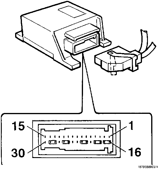
ECU Pin out
Parts & tools for this job For 1998 Fiat Seicento
- TOOLDigital multimeterSearch: automotive digital multimeter
- PARTAssorted fuse kitSearch: car fuse assortment kit
- TOOLWire crimper and connector kitSearch: wire crimper connector kit
Links open Amazon search results in a new tab. As an Amazon Associate I earn from qualifying purchases.